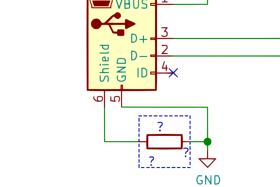
question: you have a USB connector on your project. how do you connect the shield? justify your answer, reply to the thread. (click this thread for the poll)
how do you connect the shield ground to the board's digital ground? justify your answer.
by "justify your answer" i just mean "explain why, as if to an engineering student or hobbyist"
the answer: it's complicated! it depends on several things
 frequency of concern
 system grounding strategy
 system design constraints (audio, sensitive circuits?)
 frequency of concern
 system grounding strategy
 system design constraints (audio, sensitive circuits?)
you need to read this book for a detailed answer. https://www.goodreads.com/book/show/19168165-electromagnetic-compatibility-engineering
i *highly* recommend it for all electrical engineers. i wish i had read it years ago.
remember that engineering is not magic--it is based on the principles of physics.
like many engineering problems, there are tradeoffs. this is one area where "cargo cult design" is not going to work.
but if you're not designing a commercial product and you don't have to worry about EMI compliance, then just tie the shield to your board ground and don't worry about it.
but we can dig into a few of the details. twitter isn't really the best way to cover it though 

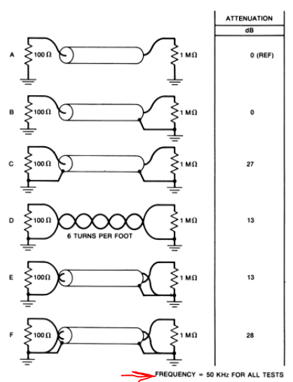
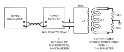
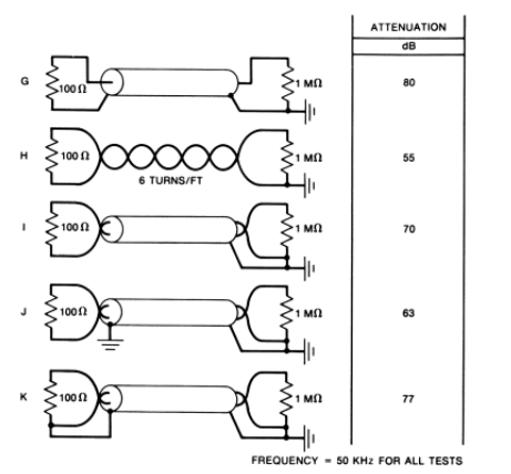
page 72 and 73 of the book have diagrams of an experiment that measures how effective the shield is for a variety of connection techniques. note that this ONLY applies for 50KHz frequencies and below.
if you study those diagrams, you can conclude that it is best to tie the shield to a conductor in the cable only on one side. BUT this is 1) only for f<50KHz and 2) systems with a separate metal chassis ground (i.e. rackmounted modules, etc)
but what about high frequencies, you might ask? shouldn't we still disconnect the shield at one end?
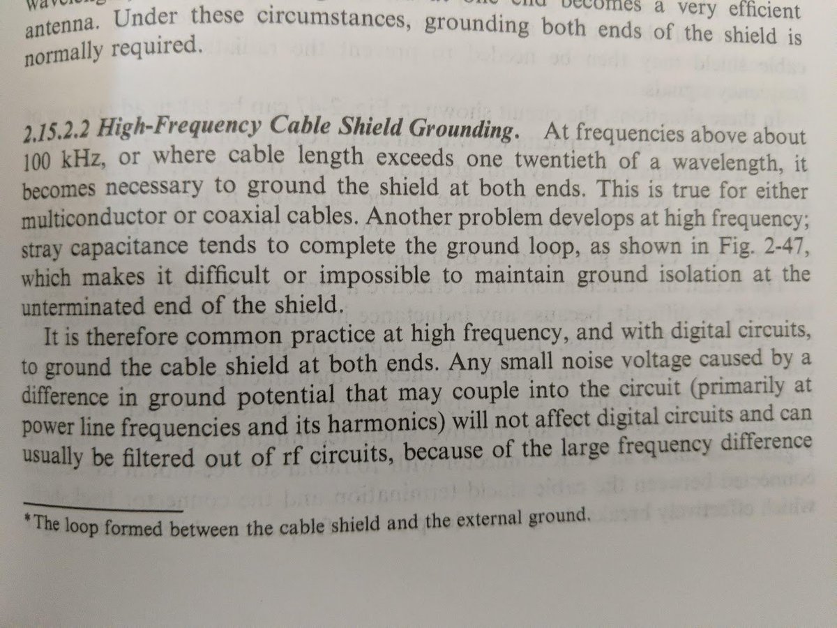
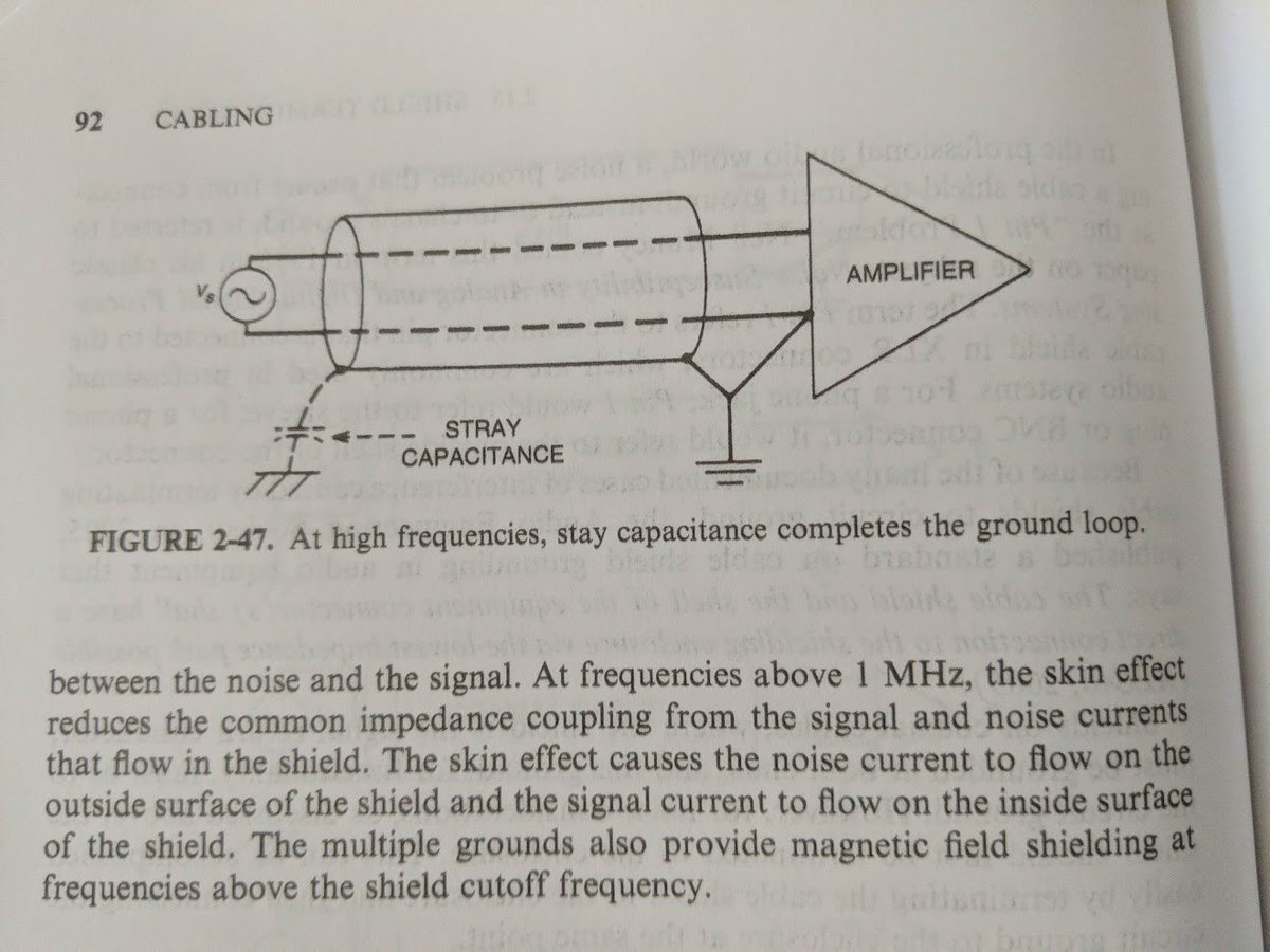
well, you can, but there's enough stray capacitance that, to RF, it *doesn't matter* and still forms a ground loop! but this is still OK...
due to the skin effect, external RF noise currents will travel along the *outside* of the shield and internal signal return currents will travel along the *inside* of the shield! it means they interact hardly at all.
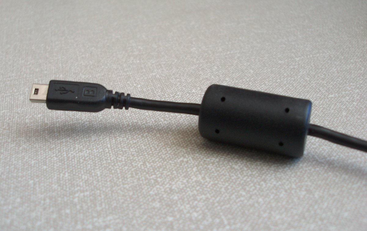
so what about those ferrite beads on a cable? they turn the cable's shield into an inductor, increasing the impedance and reducing the RF current that may be traveling along it.
in my experience with complex interconnected systems, this can turn into a game of whack-a-mole as the RF return current will find a path back (oh yes it will!) using a different route--and it may be a less desirable one!
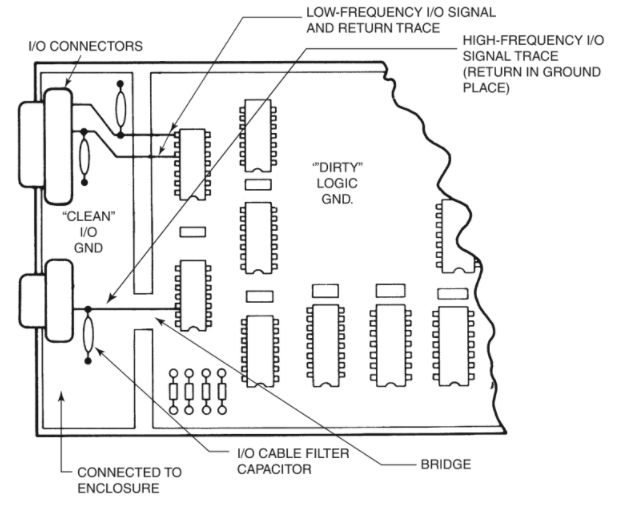
page 486 of the book sets up a nice concept relevant to our problem at hand. create a "clean" I/O ground area on the PCB that acts like an extension of the chassis. put your EMI filter parts here. the idea is to direct any EMI on the signals  to the shield ground return.
 to the shield ground return.
the nasty, high frequency switching currents on the digital ground plane are more or less walled off by the cuts in the ground. note that they still must be connected so that high speed signals have a return path. that's what the bridge does.
the thing works *only* if you have a low-inductance connection between the I/O ground and the chassis. lots of metal to metal contact using spring fingers, brackets, connector shield brackets, and so on. electrically, they must look like a big wide low impedance connection.
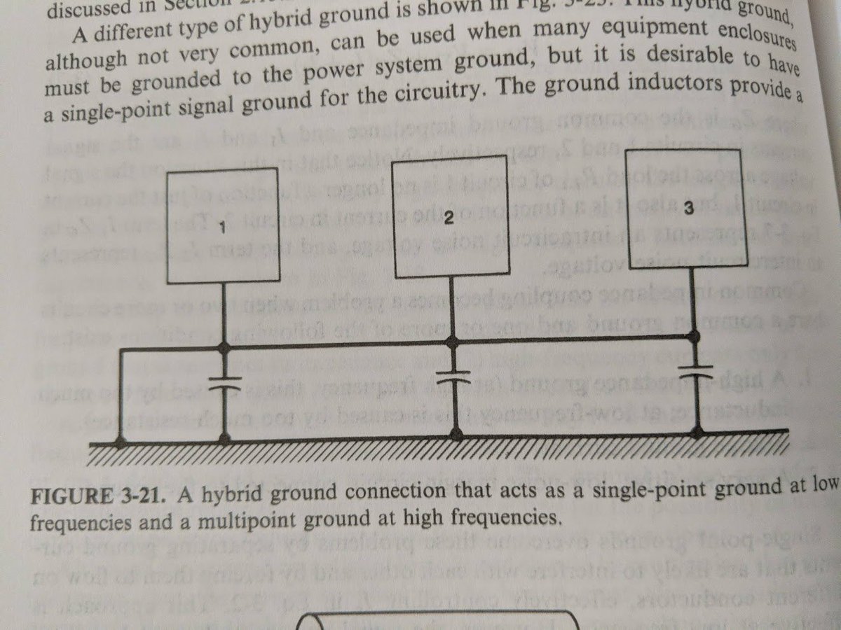
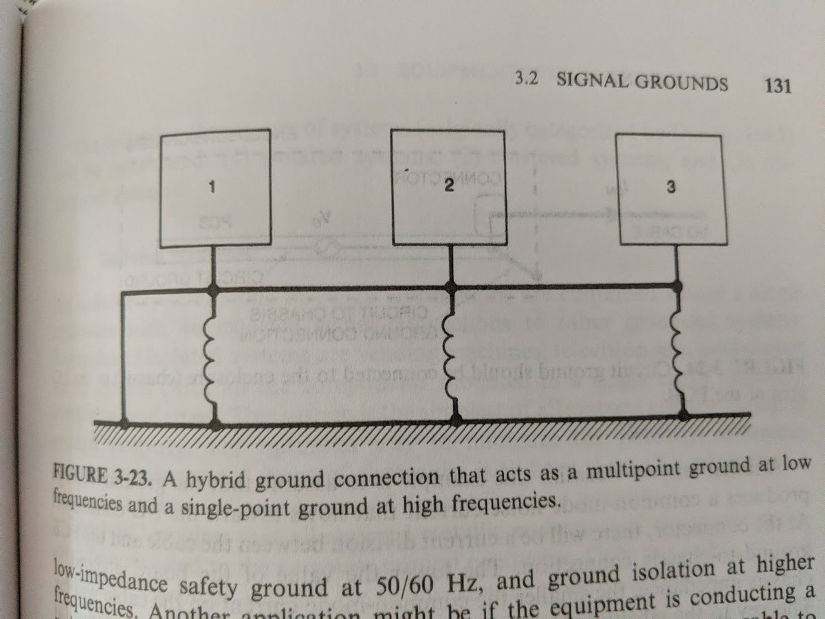
what about the thing with the shield ground tied with a capacitor or inductor in series? this is part of a *system* of multiple units connected together, and it's called a hybrid ground.
with a capacitor between the grounds, you're creating a system that disconnects the ground for low frequencies (targeting a single point ground with no ground loops) but shorts the grounds together at high frequencies (providing return paths for RF)
so whenever i see someone put a capacitor or inductor in between their USB shield ground and board ground, i tell them "oh you've chosen a hybrid grounding scheme. what's the system diagram look like? where's your single point ground connection?"
anyway i have barely scratched the surface of the topic. it gets really complicated! if any of this is interesting to you, i recommend you go read the Ott book. it's very, very good.

 Read on Twitter