Nerd thread, mute away if you’re not into it.
Installing a backlit LCD and making some repairs to the Casio CZ-101.
If you’ve never opened one of these and looked under the hood, they are the absolute worst; reader beware you’re in for a scare.
Installing a backlit LCD and making some repairs to the Casio CZ-101.
If you’ve never opened one of these and looked under the hood, they are the absolute worst; reader beware you’re in for a scare.
The horror!
First step: desolder the battery wires so we can get the backplate out of the way at least.
Ngl, 1/2 the reason I’m posting is so I have a pic of where those wires go when it’s time to close.
First step: desolder the battery wires so we can get the backplate out of the way at least.
Ngl, 1/2 the reason I’m posting is so I have a pic of where those wires go when it’s time to close.
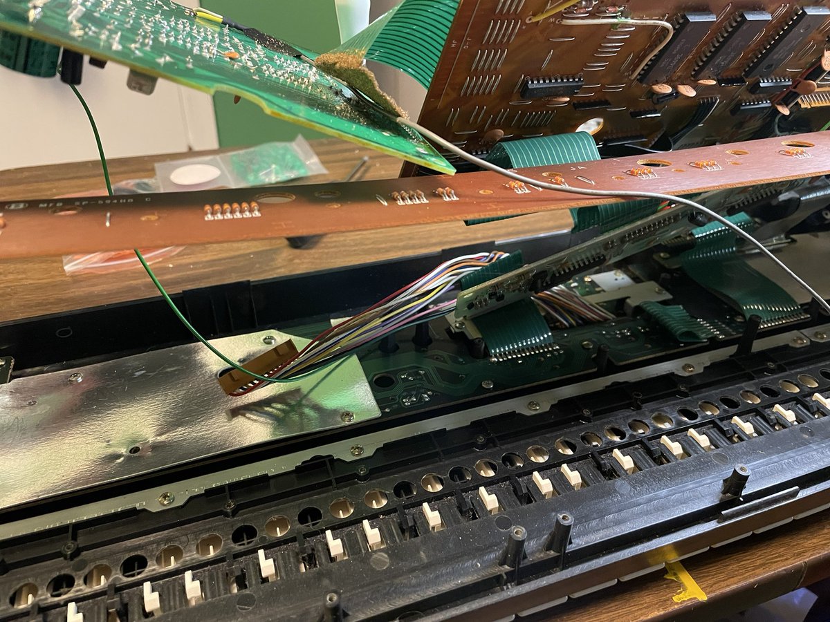
Getting kinky and suspending the first layer of boards to make this easier to work on.
Stole this idea from the guy who made the mod kit, my only addition is using a mic stand to suspend them from.
That brown connector is what we’re after for the display.
Stole this idea from the guy who made the mod kit, my only addition is using a mic stand to suspend them from.
That brown connector is what we’re after for the display.
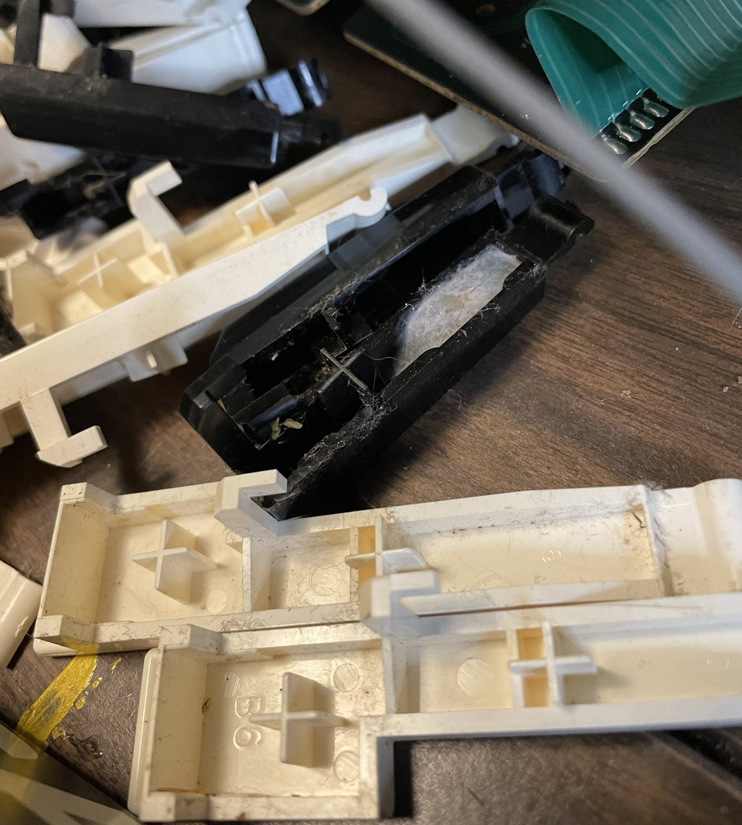
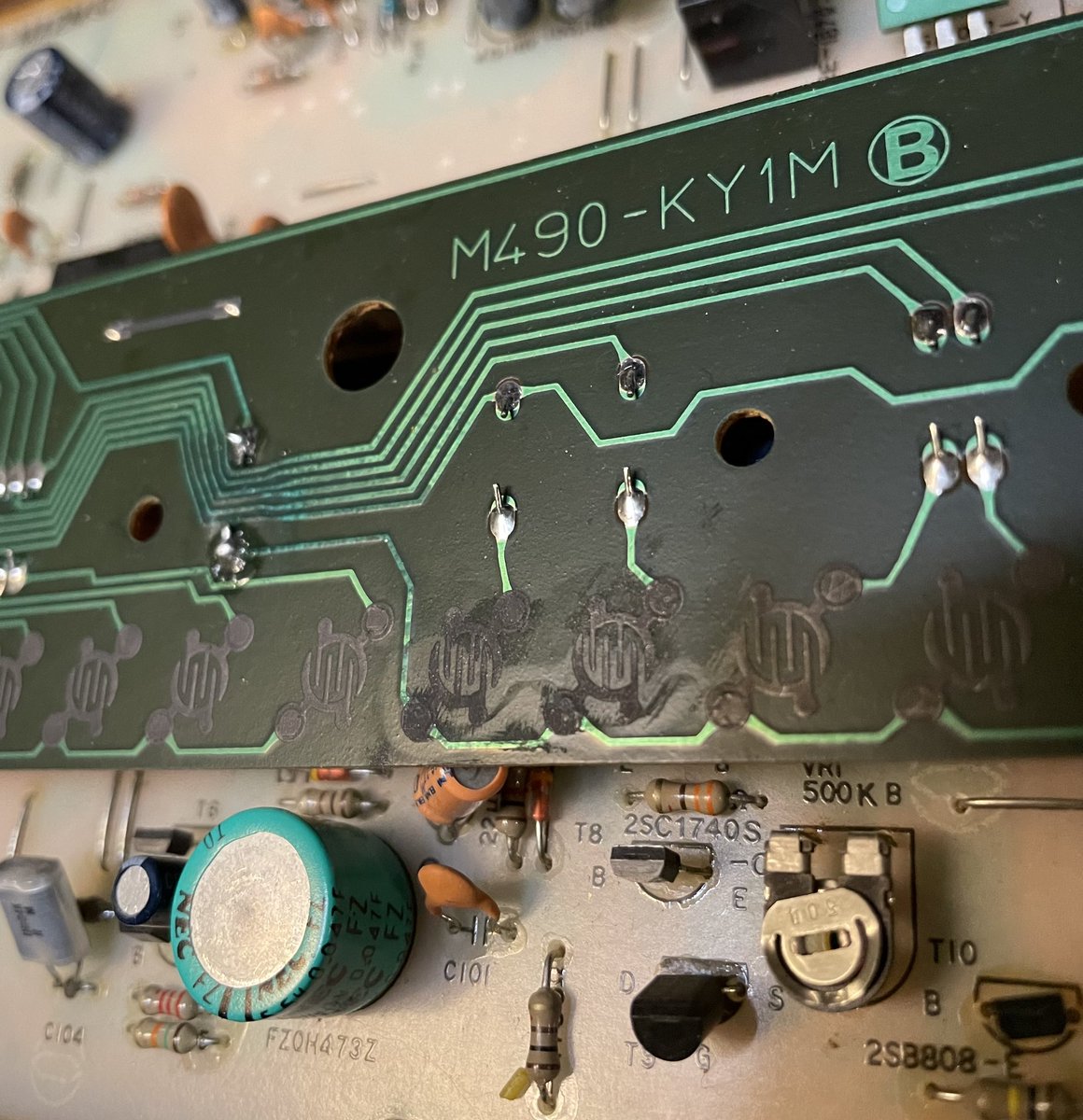
Ooof. That explains the wonky keys. I’ll have to see if there’s anything I can do for those contact pads in the upper left, but definitely need to check those traces
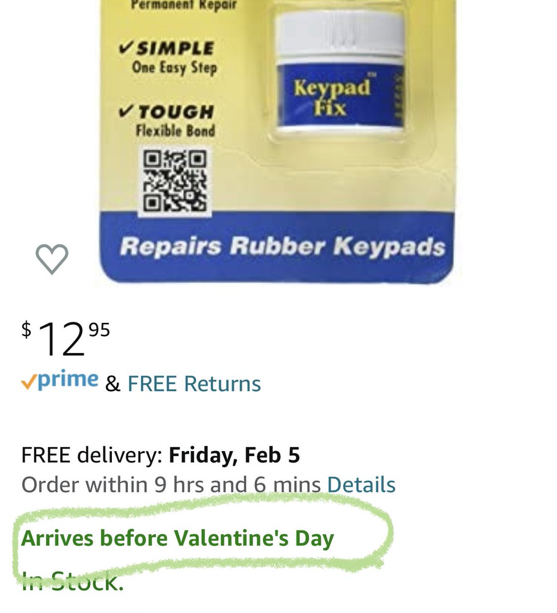
Excellent news if anyone needs a romantic gift that won’t break the bank 
Downside, the 101 is gonna be on my desk longer than I’d hoped waiting for this stuff. But worth it not to open it up twice

Downside, the 101 is gonna be on my desk longer than I’d hoped waiting for this stuff. But worth it not to open it up twice
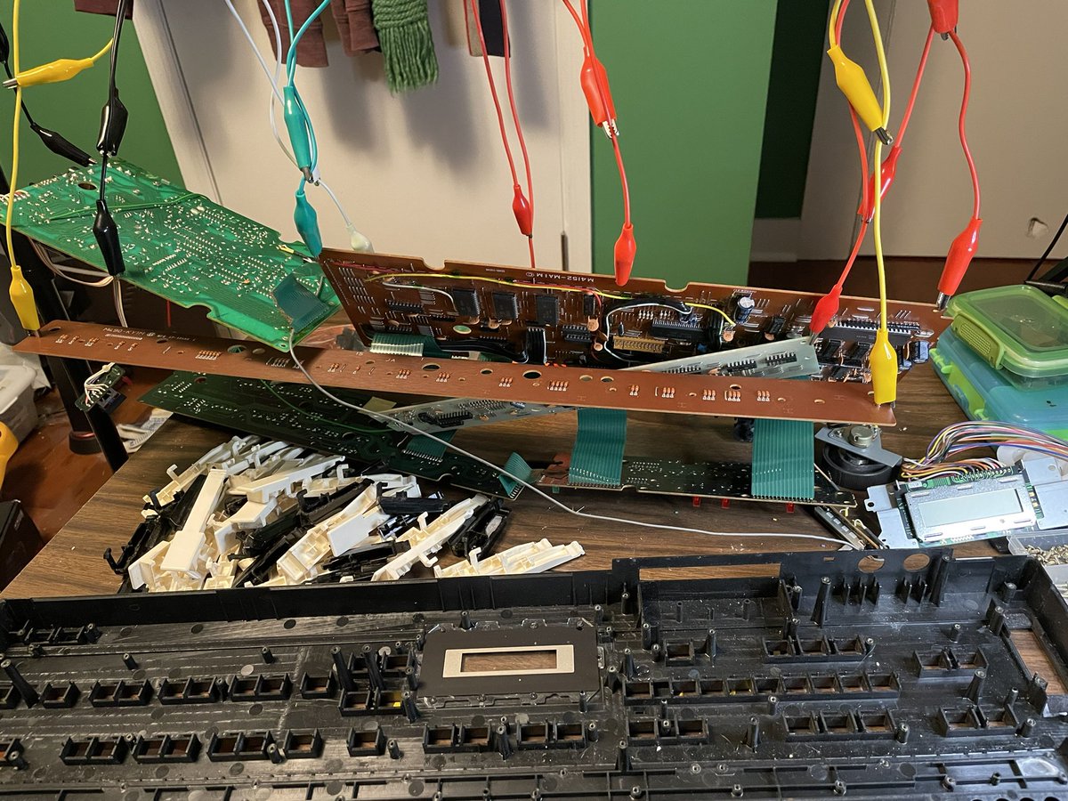
It’s apart! So much 80s dust. Giving it good clean next.
Last time I took it apart I had no idea what I was in for so didn’t strip it all the way down and wash it.
The plan is to give it to a friend though, so I should probably clean out the actual spider nests. I guess.
Last time I took it apart I had no idea what I was in for so didn’t strip it all the way down and wash it.
The plan is to give it to a friend though, so I should probably clean out the actual spider nests. I guess.

The green LED that shows you which patch bank is selected doesn’t work. My first thought was this nasty looking trace, but I’ve got good continuity.
This might be the fist time I’ve encountered an LED that’s actually just burnt out?
This might be the fist time I’ve encountered an LED that’s actually just burnt out?
Well I’ll be. Popped in a new LED and it works fine.
A first for me, but sometimes it really is just lupus I guess
A first for me, but sometimes it really is just lupus I guess

Next up, replaced the audio and power jacks with shiny new ones that came with the LCD kit.
The old audio jacks I can recycle cause they weren’t too bad, but the old power jack was gnarly.
Probably gonna replace some caps and call it a night, take on the LCD tomorrow
The old audio jacks I can recycle cause they weren’t too bad, but the old power jack was gnarly.
Probably gonna replace some caps and call it a night, take on the LCD tomorrow
Color me salty.
I got a mod kit since I didn’t want to bother figuring out the mounting hardware and wiring myself.
But apparently neither did the person who made the kit. The wiring and hardware instructions are for two different boards neither of which match the one I got
I got a mod kit since I didn’t want to bother figuring out the mounting hardware and wiring myself.
But apparently neither did the person who made the kit. The wiring and hardware instructions are for two different boards neither of which match the one I got

Since the original display works, a smart person would just feel silly about paying $20 for new jacks and go on about their day.
But I have a 3D printer whose purchase I still need to justify, so let’s see if we can’t design a new bracket.
Gotta love project creep!
But I have a 3D printer whose purchase I still need to justify, so let’s see if we can’t design a new bracket.
Gotta love project creep!
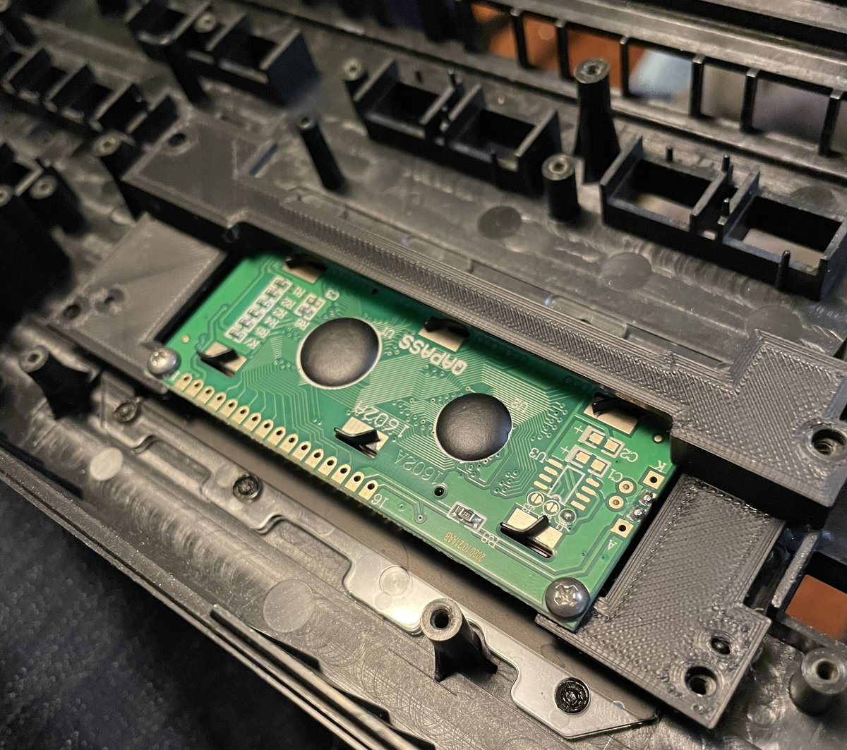
Hey my custom bracket fits? On the first try? 
If this works I’ll put the files/instructions out there so anyone else who wants to do this can save a few bucks and/or have a nicer mounting solution.

If this works I’ll put the files/instructions out there so anyone else who wants to do this can save a few bucks and/or have a nicer mounting solution.
My hubris was too great. Bracket fit but was holding the lcd up a tiny bit too high. Adjusted the file to bring it down 1.5mm so I’ll check back in a few hours and see if we’re on the money with round 2.
Version 2 has some structural integrity issues, I managed to break off one of the mounting plates, then broke it again after gluing it back 
But it appears to line up just right. I’m gonna go ahead wire up the screen to be sure before I make a final beefier version.

But it appears to line up just right. I’m gonna go ahead wire up the screen to be sure before I make a final beefier version.
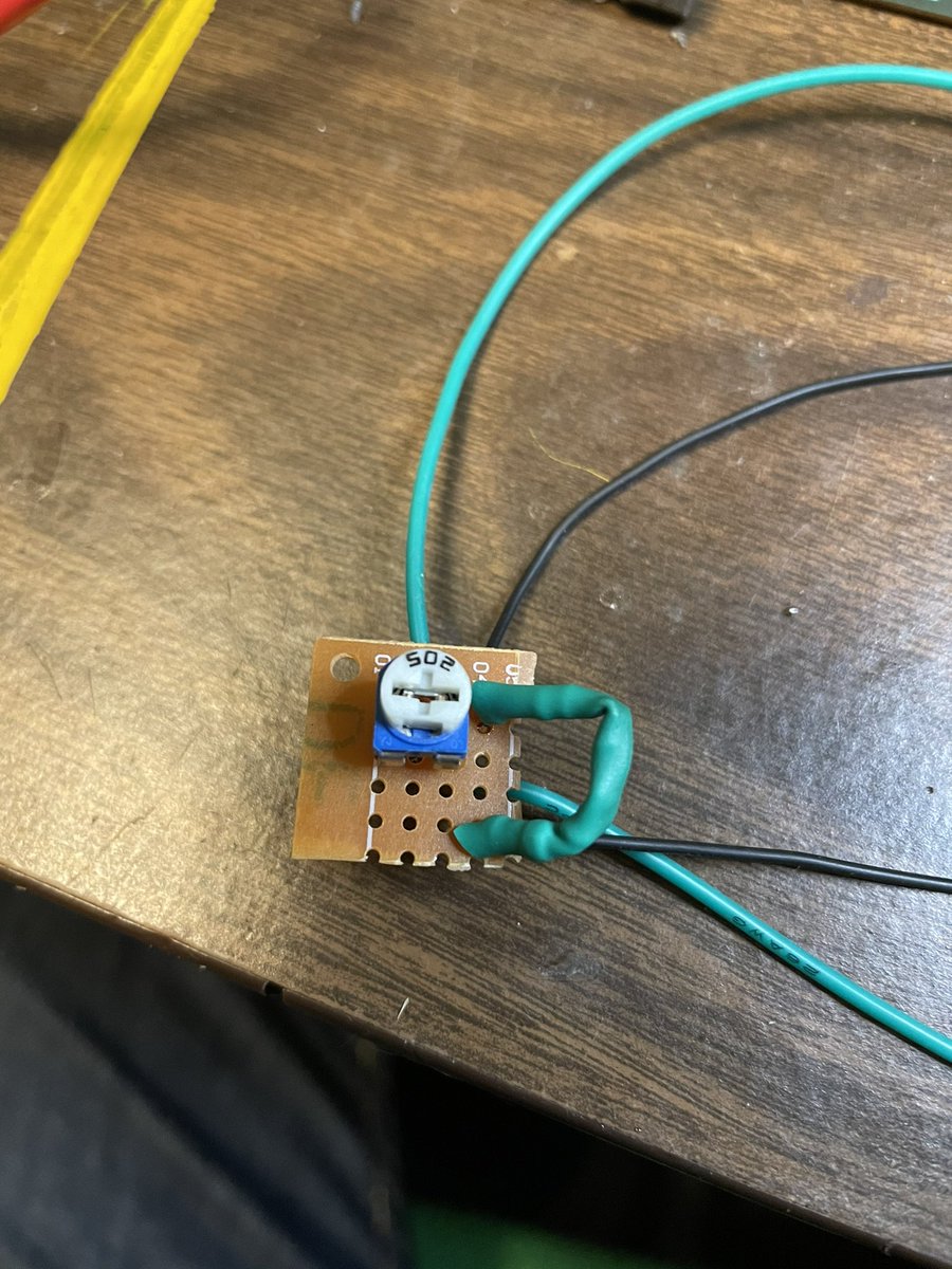
When wiring the new screen, a 65 Ohm resistor (or 2 resistors adding up to that value in this case) is used to jumper the LCD power pin to the Backlight power pin.
I’m also installing a 5k trim pot between the blue wire and the new LCD as a contrast control.
I’m also installing a 5k trim pot between the blue wire and the new LCD as a contrast control.
Put these a lil board. I’ll find a place to mount it to the bracket so I don’t mess with any original parts.
For reference, the black wires are the power jumper, the green wires will insert the pot between the blue wire and pin 3 of the LCD
For reference, the black wires are the power jumper, the green wires will insert the pot between the blue wire and pin 3 of the LCD
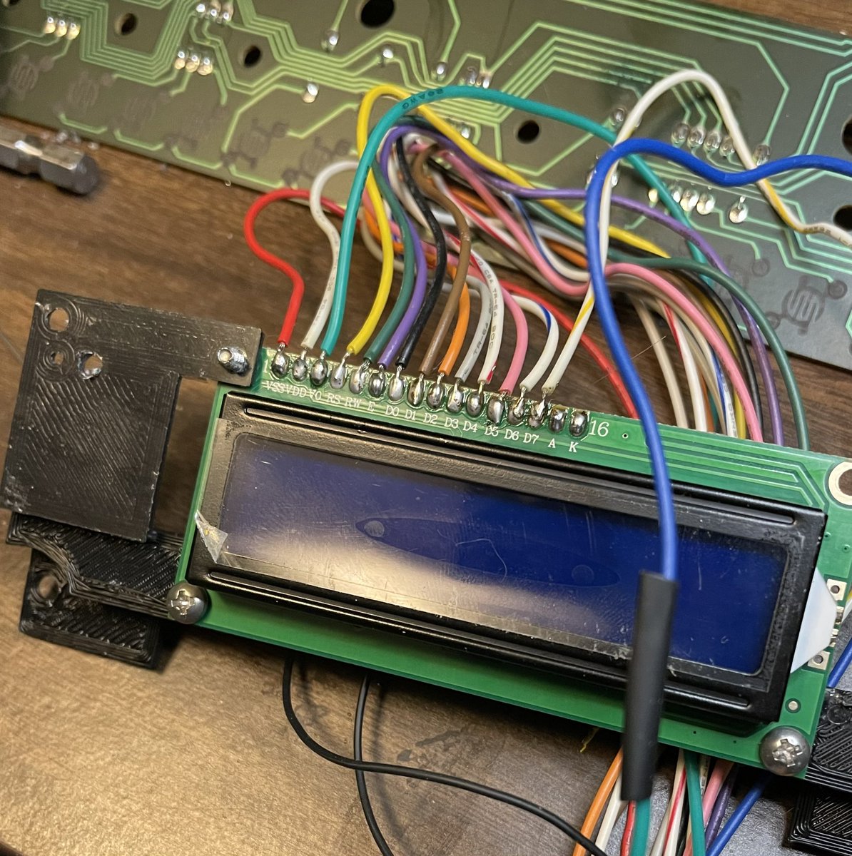
Screen wired up! Easy enough, Pins 1-14 on the new board line up with the 14 wires from the old screen (same order).
Pins 15 and 16 are jumpered to pin 2 and pin 1 to provide power and ground connections for the backlight (respectively).
Pins 15 and 16 are jumpered to pin 2 and pin 1 to provide power and ground connections for the backlight (respectively).
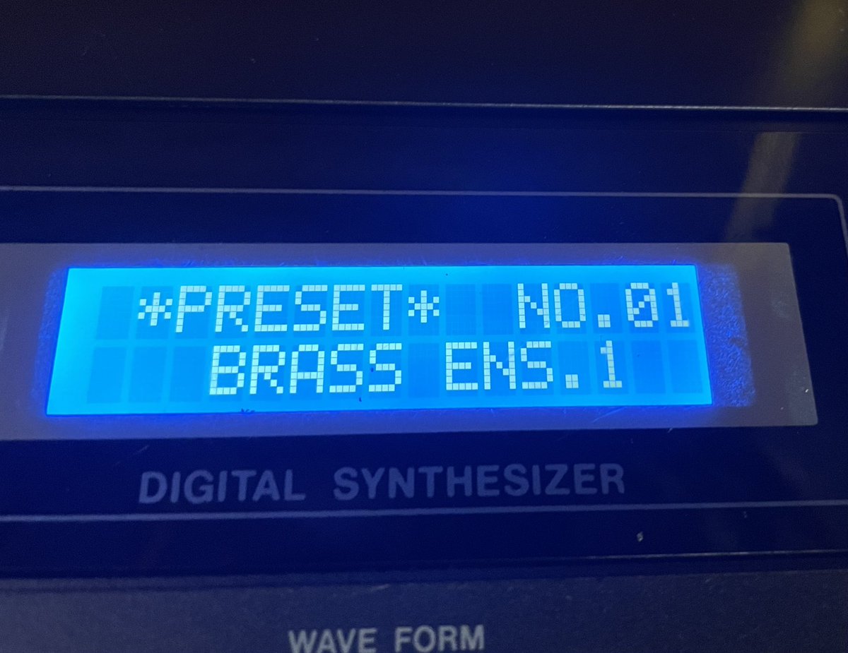
Hey it even works!
The contrast adjustment works nicely too
The contrast adjustment works nicely too

Here’s how the pads turned out. I feel like I did a really bad job with that carbon coat stuff but hopefully it’ll work?
All those nasty traces are good, so once the bracket is done printing it should be ready to go back together
All those nasty traces are good, so once the bracket is done printing it should be ready to go back together
Bracket is in, and the CZ is mostly reassembled!
The wires attach to the top of the new board, so they route around like this to avoid the battery compartment above.
Last step is to mount the contrast control and we should be all set!
The wires attach to the top of the new board, so they route around like this to avoid the battery compartment above.
Last step is to mount the contrast control and we should be all set!
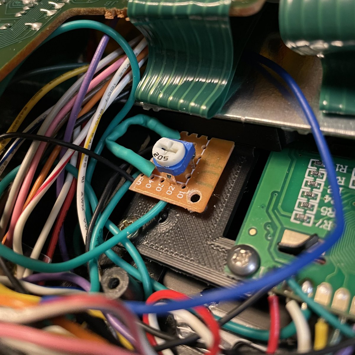
Control mounted with a blob of hot glue.
It’s mounted to the 3D printed bracket not the actual keyboard, so everything we’ve done is non-destructive and this synth can be restored back to factory if the owner wants to down the road.
It’s mounted to the 3D printed bracket not the actual keyboard, so everything we’ve done is non-destructive and this synth can be restored back to factory if the owner wants to down the road.
It’s done!
Always love how much big gritty sound you can get out of the CZs. Especially coming out of the lil 101
Always love how much big gritty sound you can get out of the CZs. Especially coming out of the lil 101

 Read on Twitter


