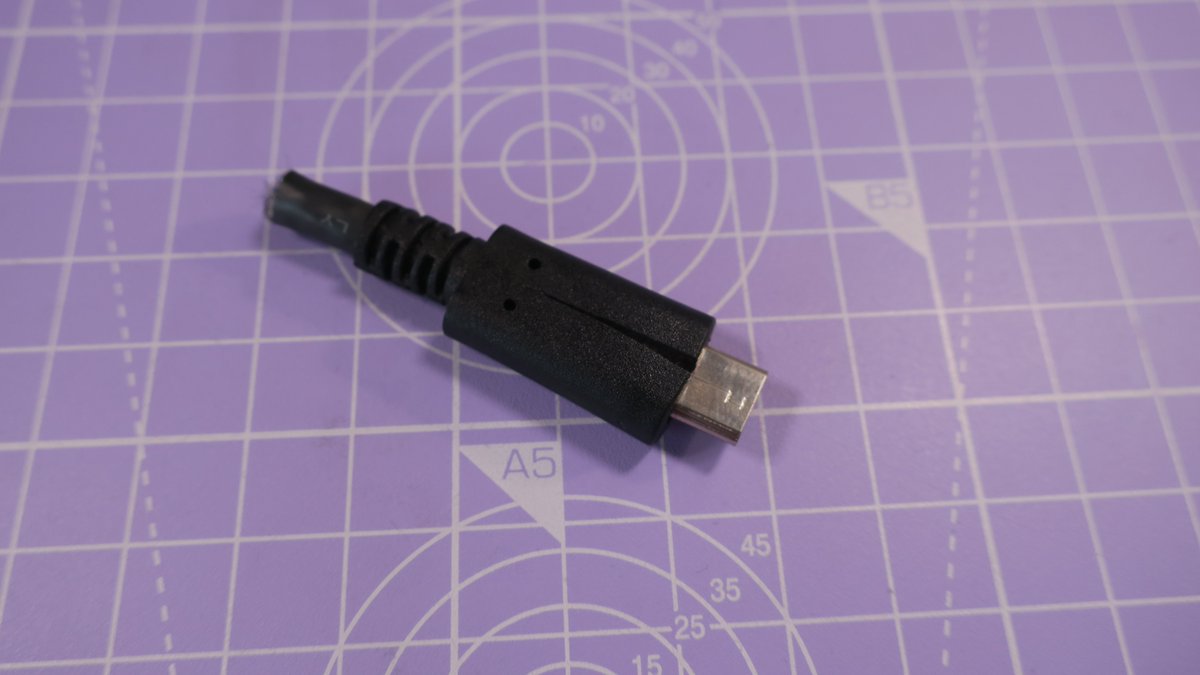
I had this cut off USB Type-C Plug from a 10Gbps cable, anyone feels like a teardown thread? Maybe we can find out why those cables are so darn expensive!


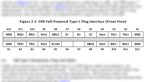
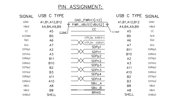
The cable is a Multicomp Pro MC000998, it comes with a datasheet that shows how the pins are internally arranged, convenient.
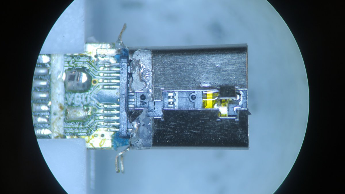
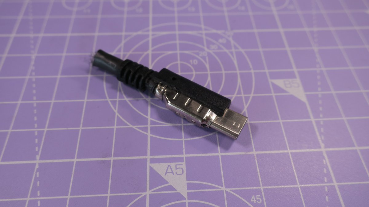
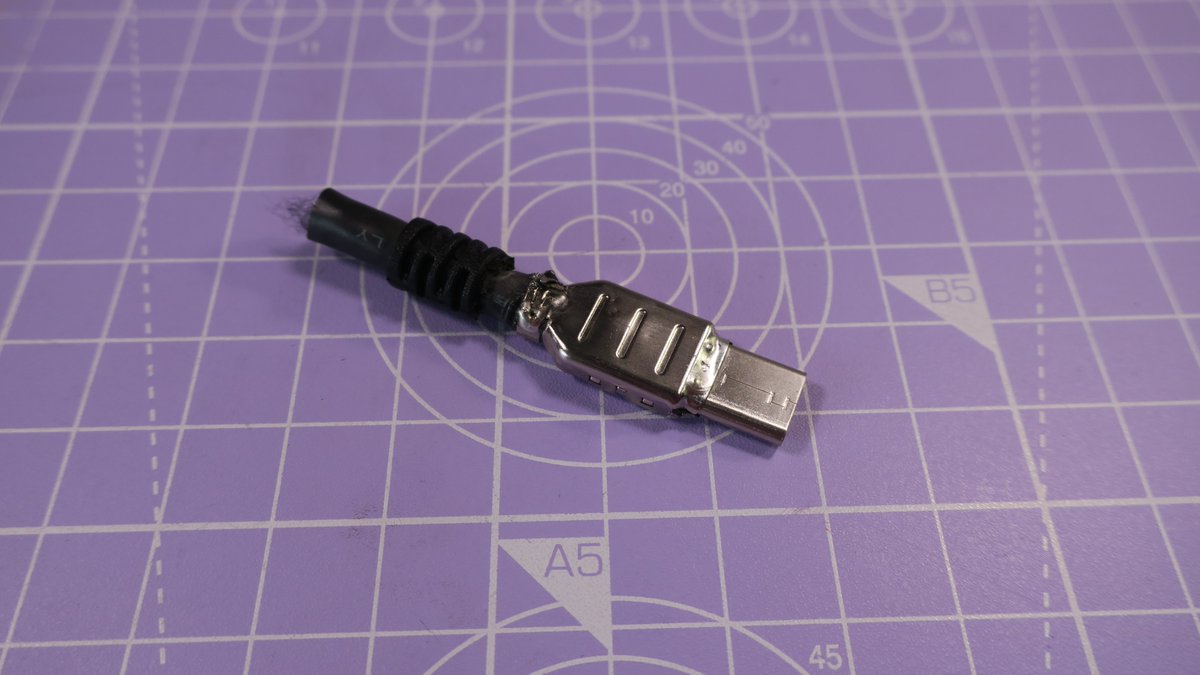
The internals are shielded so we can cut into the outer cover without worrying about cutting cables. The metal shield is soldered to the plug itself.
Inside the shield we find a PCB with a bit of kapton tape. You can find hundreds if not thousands of similar Plug + PCB sets on Aliexpress, they seem to be designed for cables like this. We also see the capacitor shown in the datasheet.
Here's a shot of all the cables exposed.
USB 2 is the white+green twisted pair in the center.
The USB 3 pairs all have an extra GND wire added in the shielding.
The yellow and blue wires are the sideband channels.
The brown and gray wires are CC and VCONN.
USB 2 is the white+green twisted pair in the center.
The USB 3 pairs all have an extra GND wire added in the shielding.
The yellow and blue wires are the sideband channels.
The brown and gray wires are CC and VCONN.
A closer look at the PCB. Worth noting is that two wires are used for VBUS, to be able to carry more current (USB PD can negotiate up to 20V@5A [!!]). Interesting to see the footprints for adding pulls to either GND or VBUS for the CC pin.
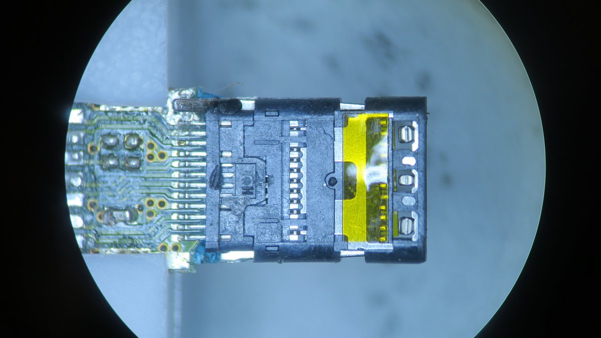
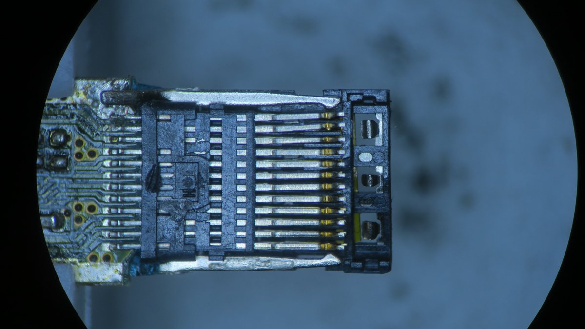
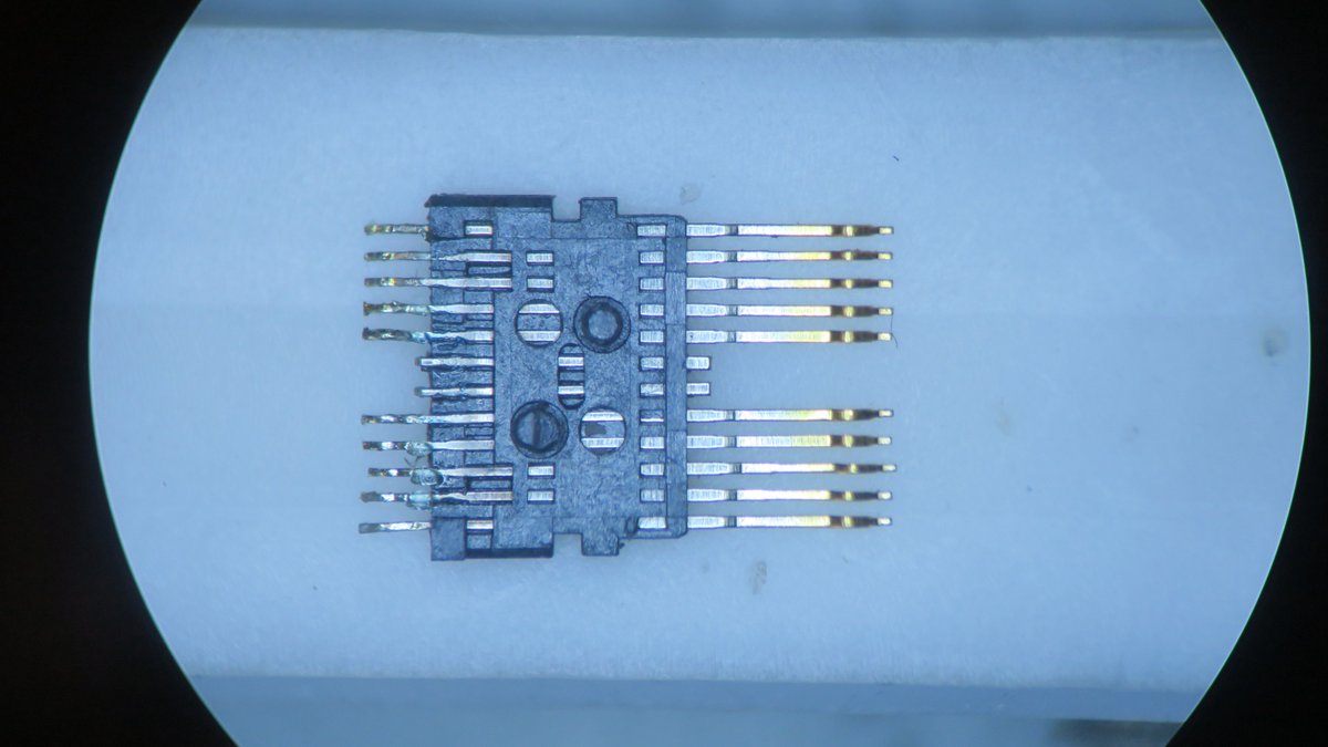
The wires are held in place by a piece of plastic that makes sure they are aligned so they can be soldered directly to the PCB. Also note that only one pair of USB 2 data pins is actually present, as per spec, it's up to the Receptacle to connect them together.
Looking at how complicated the plug is, how many different parts it contains, it's no surprise that they are somewhat expensive.
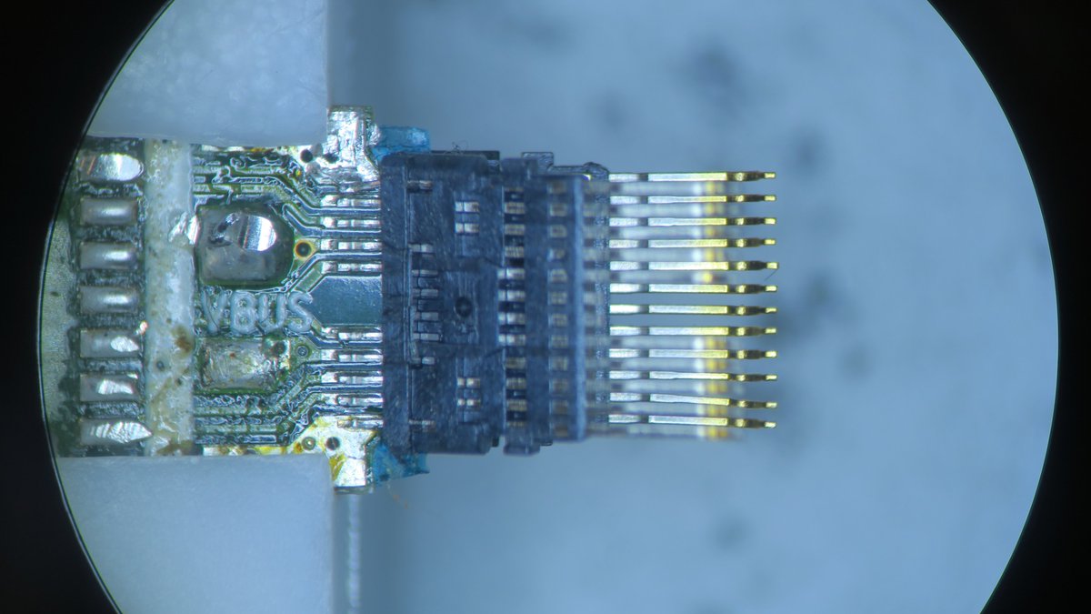
The top and bottom covers of the plug come off just like that, it was the metal shield holding them in place. With those off, we can see all the tiny metal springy pins that mate with the pads in the Receptacle.
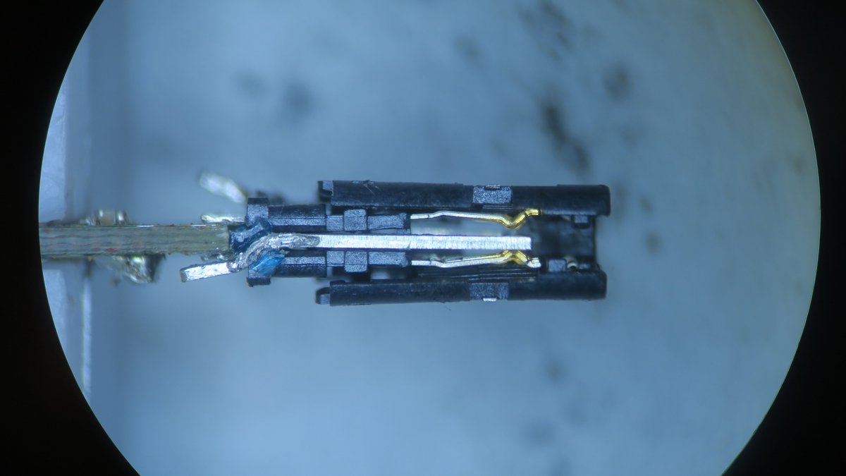
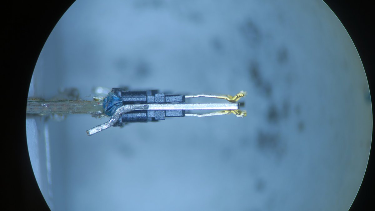
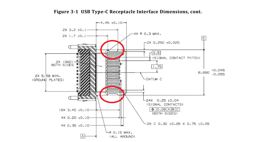
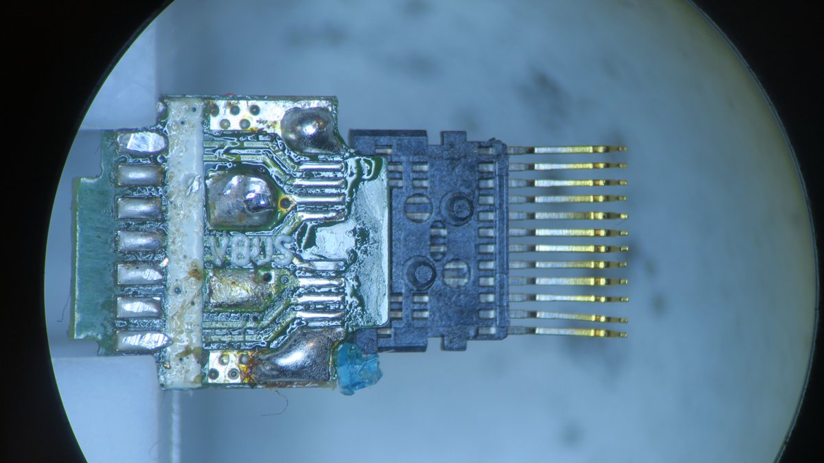
Once the top and bottom parts are removed, we can separate the internal parts, again held together by nothing, just plastic for alignment. Between them we find a metal part that is responsible for keeping the Plug latched inside the Receptacle (last image).
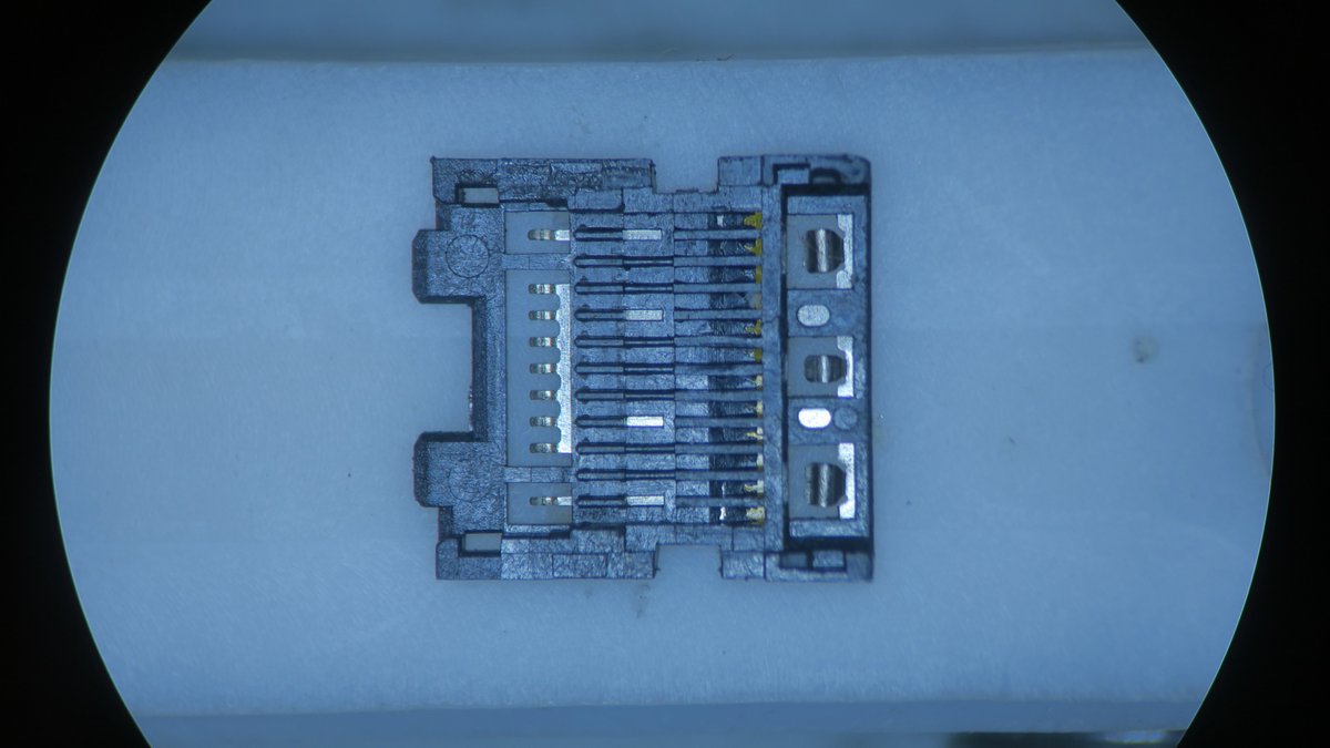
And lastly, we can remove what is left of the plug off the PCB, two separate parts, nearly identical except one side doesn't have the USB 2 data pins as mentioned previously.
That concludes the thread, hope you had fun, maybe in the future, we can tear down a 10Gbps Receptacle :)

 Read on Twitter


![A closer look at the PCB. Worth noting is that two wires are used for VBUS, to be able to carry more current (USB PD can negotiate up to 20V@5A [!!]). Interesting to see the footprints for adding pulls to either GND or VBUS for the CC pin. A closer look at the PCB. Worth noting is that two wires are used for VBUS, to be able to carry more current (USB PD can negotiate up to 20V@5A [!!]). Interesting to see the footprints for adding pulls to either GND or VBUS for the CC pin.](https://pbs.twimg.com/media/Es_AukWXIAUNP0n.jpg)
![A closer look at the PCB. Worth noting is that two wires are used for VBUS, to be able to carry more current (USB PD can negotiate up to 20V@5A [!!]). Interesting to see the footprints for adding pulls to either GND or VBUS for the CC pin. A closer look at the PCB. Worth noting is that two wires are used for VBUS, to be able to carry more current (USB PD can negotiate up to 20V@5A [!!]). Interesting to see the footprints for adding pulls to either GND or VBUS for the CC pin.](https://pbs.twimg.com/media/Es_AvBXXMAAYXT-.jpg)
![A closer look at the PCB. Worth noting is that two wires are used for VBUS, to be able to carry more current (USB PD can negotiate up to 20V@5A [!!]). Interesting to see the footprints for adding pulls to either GND or VBUS for the CC pin. A closer look at the PCB. Worth noting is that two wires are used for VBUS, to be able to carry more current (USB PD can negotiate up to 20V@5A [!!]). Interesting to see the footprints for adding pulls to either GND or VBUS for the CC pin.](https://pbs.twimg.com/media/Es_BZsoXcAIzp44.jpg)


