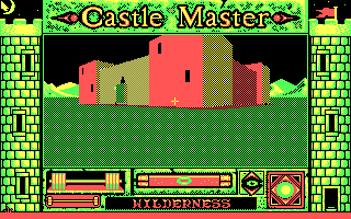
you could switch between those two ugly palettes using bit 4 of register 3D9, the "color select register"
but to find out the *exact, technical reason* we need to dig into some schematics! let me get my boots...
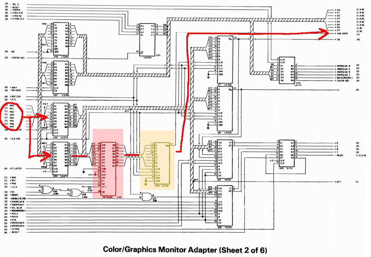
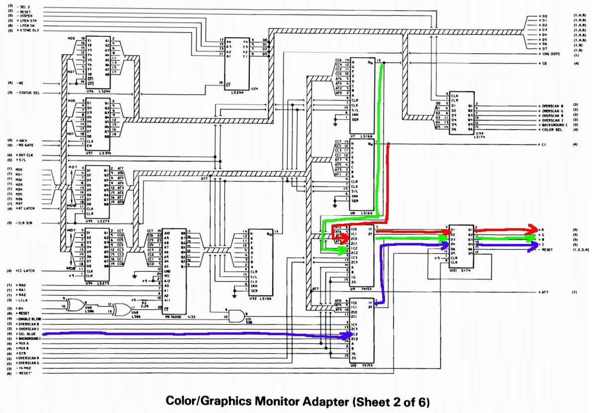
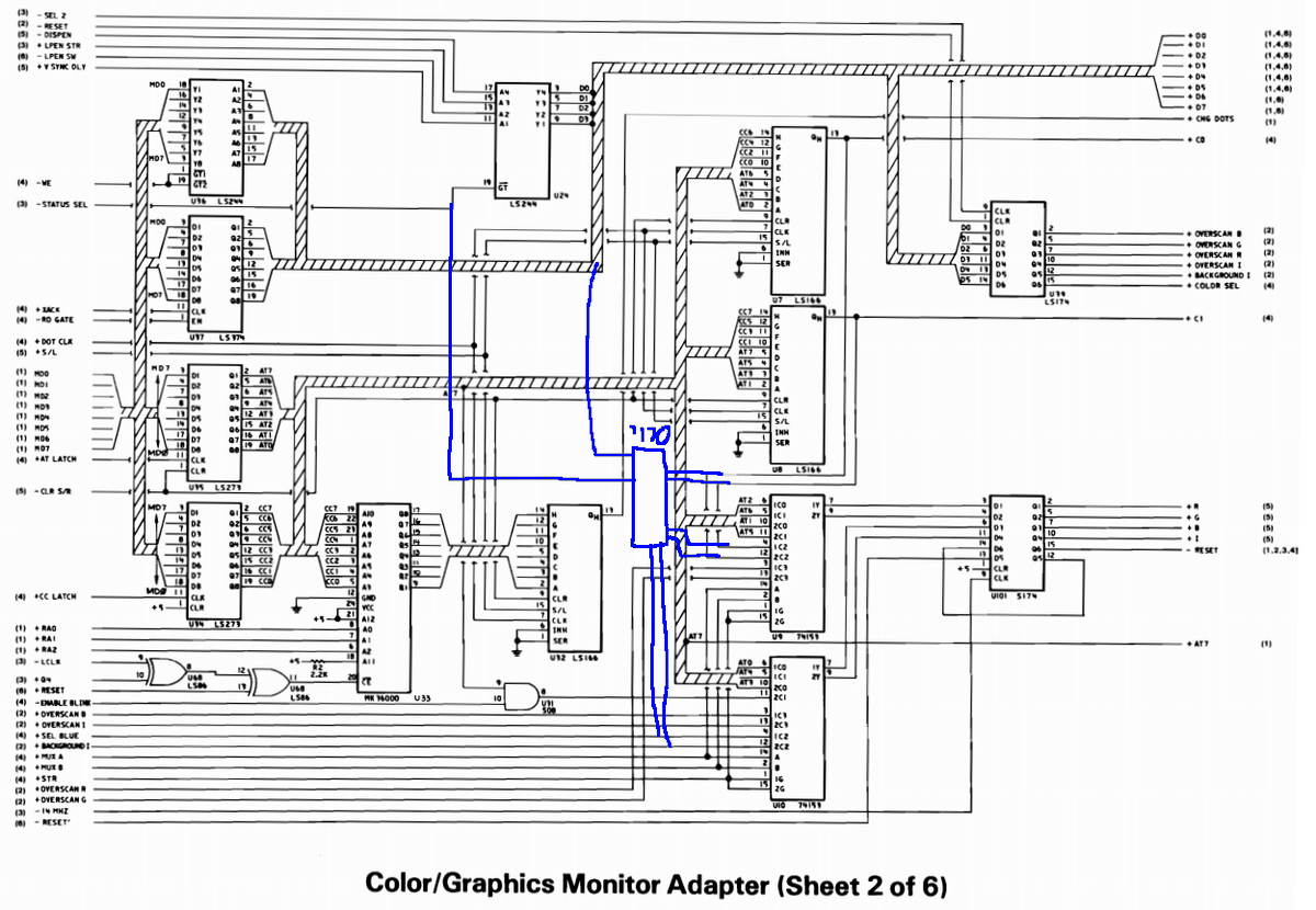
first, text mode: the character byte comes in on the left and gets latched. the attribute byte also gets latched, because they alternate in video memory: character byte, attribute, character, attribute, character, and so on.
in text mode, the character byte gets fed through a look-up table in the character ROM (red) along with the current character *row* (the font is 14 lines tall). the output of that goes into a shift register (orange) because each character is 8 pixels wide.
the attribute byte contains the foreground and background color of the character, so if current pixel = 0, you get the background color, and =1 you get foreground.
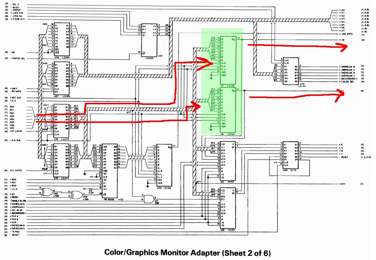
in graphics mode, things work differently. the character byte and attribute byte get fed into two separate shift registers (green). the bits are swizzled so each shift register gets 4 bits of cc and 4 bits of att. in hi-res mode, the output toggles between each shift register.
the end effect is that in hi-res monochrome mode, two bytes in the framebuffer -> 16 adjacent pixels. simple.
but what about color?
the signals from those shift registers go into a mux (mainly for text vs. graphics mode) and through a latch and out to the display, but they are mapped to the red and green channels only! blue comes from somewhere else... where could that be?
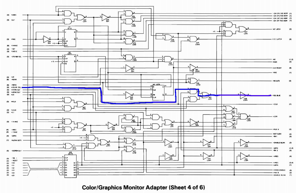
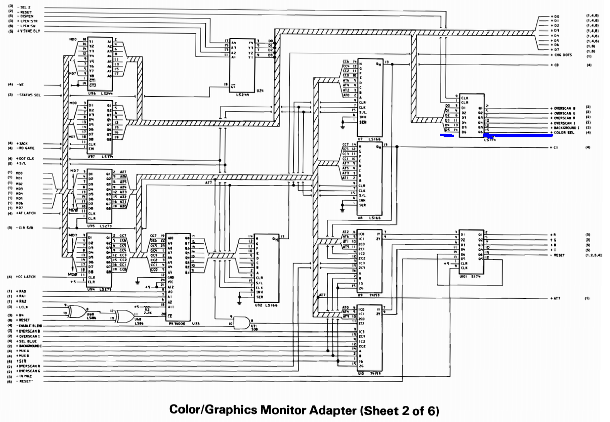
and we wind up back on the same page again! it connects to bit 5 of a register. the color select register! this is the palette select bit.
so the "palette bit" doesn't really pick a palette, it controls the blue component of the video signal! so if red/green are not both 00 (black), then the color has blue added to it. or it has no blue at all!
so you wind up with the colors on the top without blue, and the colors on the bottom with blue added. those are the two options.
but wait! with some simple wiring changes, we could swap those RGB wires around and the CGA card could have had different palettes. if the palette bit controlled green instead of blue, we'd get this:
actually these are all kind of terrible.
but what if there was another option?
some sort of...color lookup table?
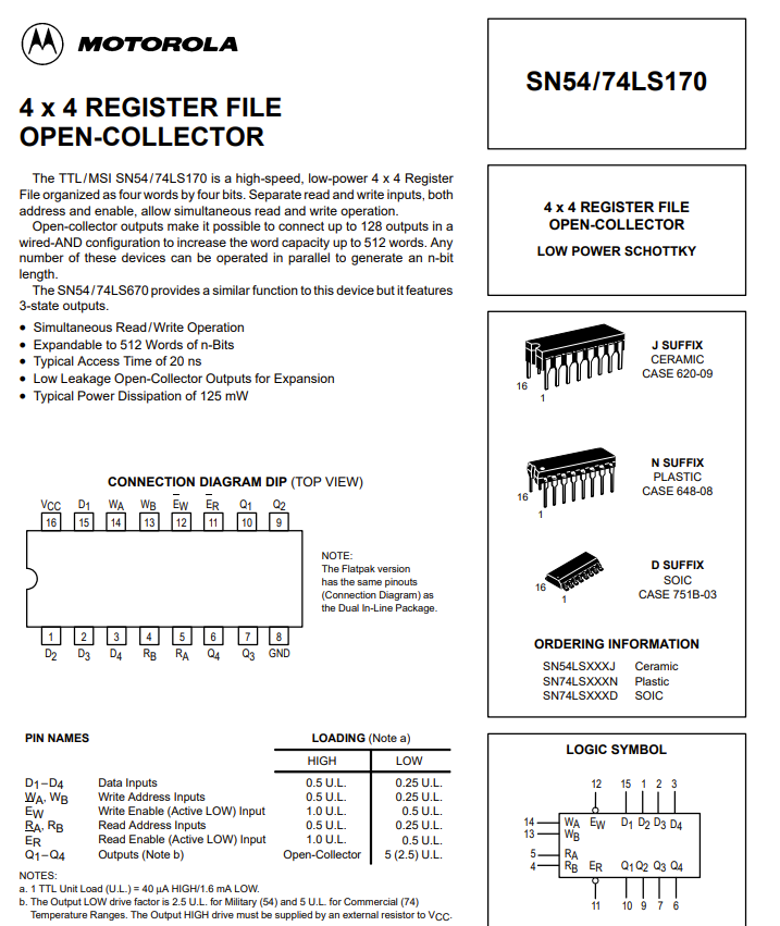
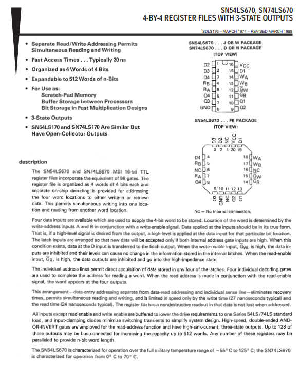
IBM could have put in a 74LS170, which is a "register file" containing four 4-bit registers. this is enough for our palette, and each color can be one of the 16 possible colors (given the RGBI digital monitor output)
but we'd need a way to *write* to the palette register. since status register 3DA is read-only, we could borrow the select line and make it so that when you write to it, the lower 4 bits select the palette position and the upper 4 bits select the resulting color.
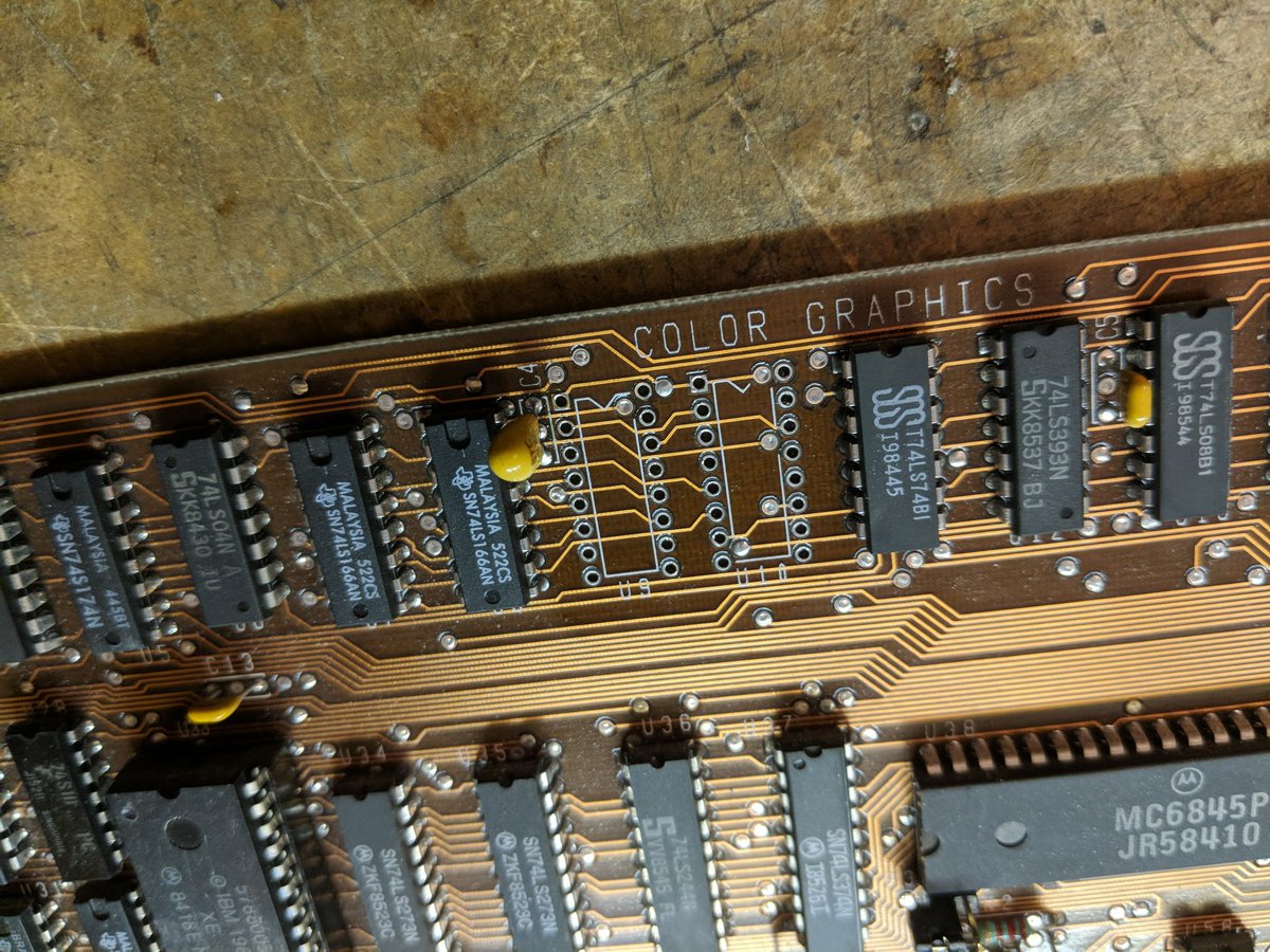
something like this. since the '170 has separate address lines for read vs. write i don't think you'd need any extra gates. just this one chip.
glancing at the schematic, i also realized that bit 4 of register 3D9 acts sort of like another palette select bit. this controls the intensity bit, I. so you either get a dark version or a light version of the two existing palettes, with one interesting exception...
so with the intensity bit turned off, the colors all darken, but yellow turns into brown instead of dark yellow. this is because the IBM CGA monitor has some circuitry that tweaks dark yellow and turns it into brown!
anyway, the palette mod looks really simple except i don't have a 74LS170 chip. i've got a few original CGA cards so next time i'm at the surplus store i'll see if they have one of those chips.
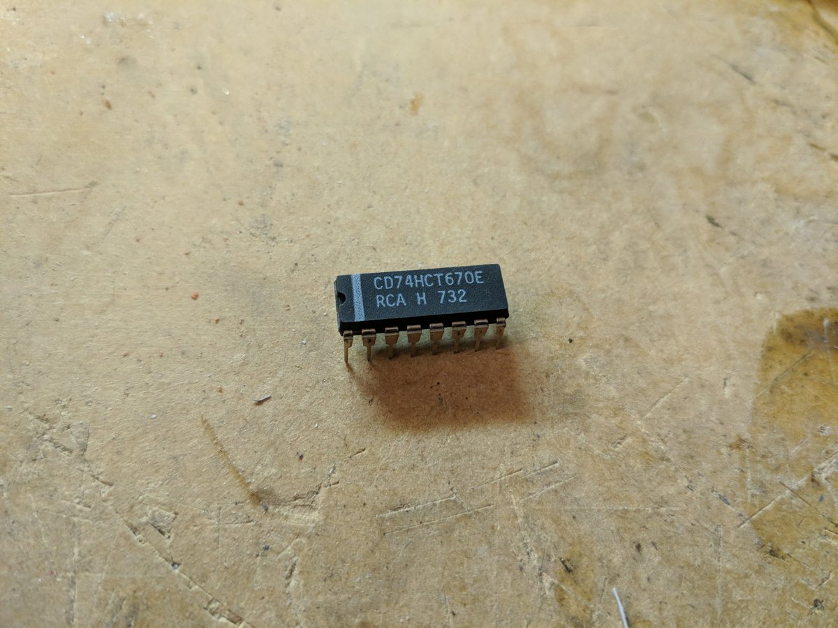
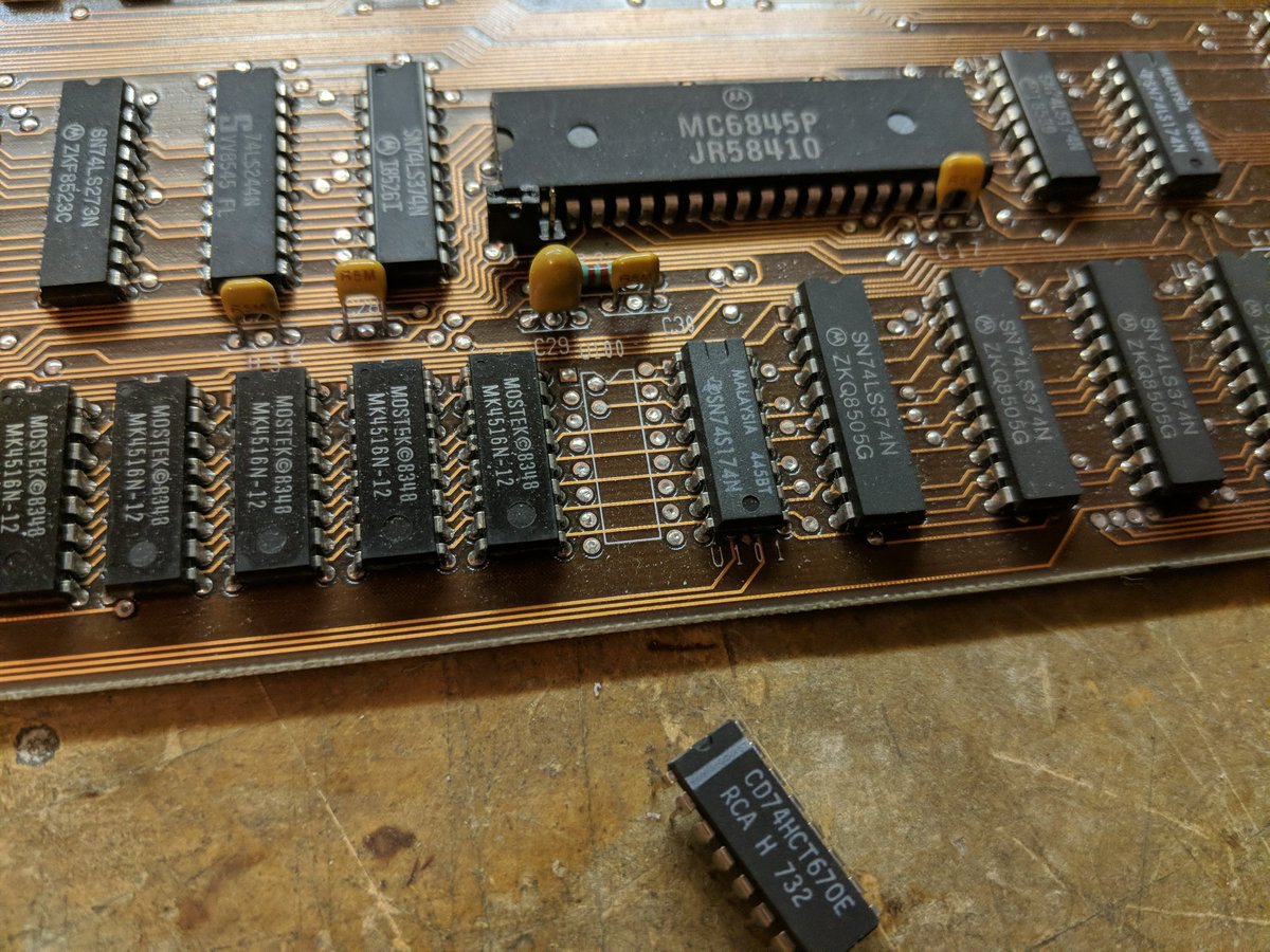
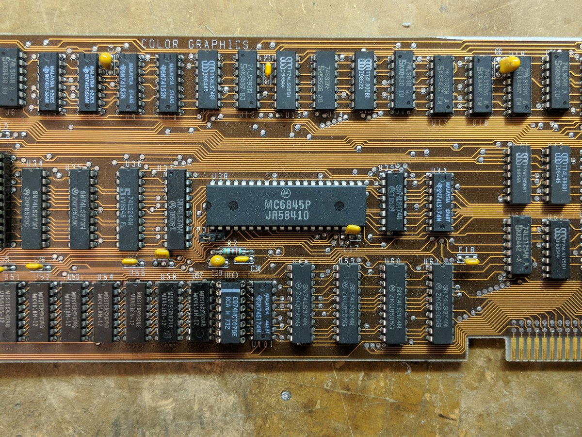
another device that could do it is the 74LS670. it's similar but instead of having open collector outputs it has tri-state outputs. funny, this part looks familiar...
and the reason it looks familiar is that Intel, in the late 1970s, was devoting a TON of resources to the iAPX432 project.
they had just finished up the 8080 CPU project and had embarked on the very ambitious 432. well, it was taking a very long time to develop, and the 8080 was only 8-bit, and they needed a 16-bit entry to compete in the market...
so a small team made some improvements to the 8080 and released the 8086, which was supposed to be a stopgap. they didn't really make specific peripheral chips for it, and they recommended that customers use the interrupt controller, DMA controller, and so on from the 8080 line.
this was a bit of a problem for the DMA controller since it only had 16 address lines whereas the 8086 (and the 8088) supported 20.
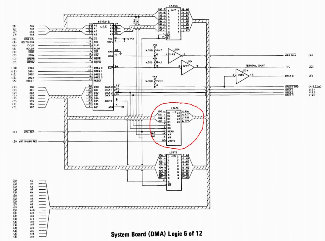
so what did IBM do? they used the 8080's DMA controller (8237) but they needed a way to store the extra 4 address bits for each DMA channel. for that, they used the 74LS670 register file chip!
this worked great. the only limitation is that the DMA controller doesn't know about this external circuit and can't increment it. so a DMA operation is limited to 64K pages (where the page is controlled by the register file chip).
unfortunately this causes issues for people doing things like writing drivers for sound cards: https://twitter.com/TubeTimeUS/status/1044711237664178177
DOS has no idea that pages exist, so when you allocate RAM, it just gives you the number of paragraphs you wanted (16 byte increments).
so people writing sound card drivers or games needed a way to allocate memory for playback buffers, and those buffers had to fit within a page and not span two pages.
apparently the most common way to do this was to allocate the block, then check the address. if it spanned two pages, then you try again. one driver i saw tried 16 times and if it still spanned two pages, it just exited to DOS with a cryptic "memory allocation" error!
well that was surely a @Foone-worthy tangent!  getting back to video, some people have been talking about CGA composite mode so let's look at that briefly.
 getting back to video, some people have been talking about CGA composite mode so let's look at that briefly.
the IBM CGA card comes with an RCA jack on the back so you can plug it directly into your NTSC television, if it can handle composite video (or an RF modulator, if it can't).
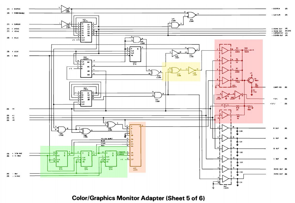
here's the circuit that generates NTSC. in red is a buffer, basically a resistor DAC. in yellow is the composite sync generator. and orange is a mux. the mux uses the RGB inputs to select between 6 different signals...
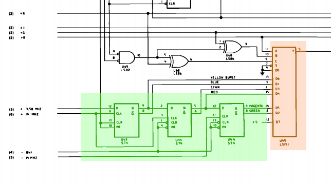
the signals come from this chain of 3 cleverly-connected flip flops. the input signals are 14.318MHz and 3.549MHz (the NTSC colorburst and 4x that frequency)
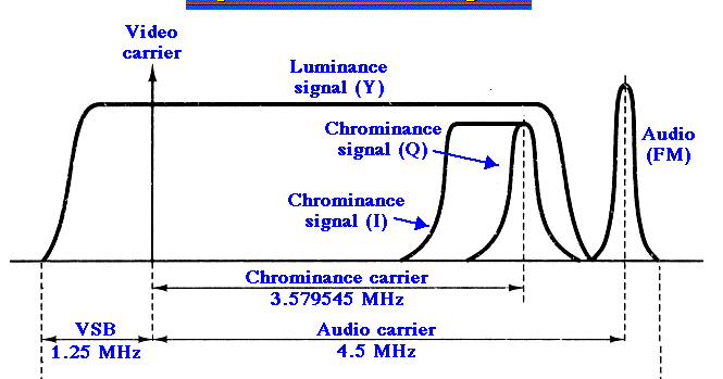
each output is a 3.579MHz square wave with a different phase relationship.
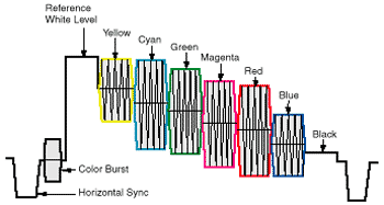
at the beginning of every NTSC video line, there's a colorburst signal. that comes from the first flip flop output signal. all the colors are determined by comparing the phase of the 3.579MHz signal to this reference.
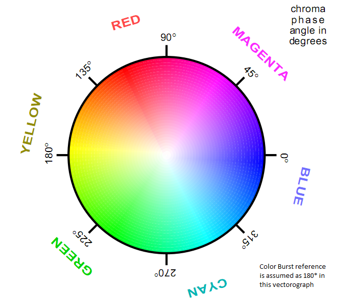
so to get yellow, we just output another square wave that's the *same* phase as the colorburst, and we get yellow. shift it by some angle, and you get a different color.
if you want, you can look at the flip-flop circuit and figure out what phase shift gets created for each color. (fyi, the -14MHz signal is just the inverted version of that clock; the minus sign indicates logical inversion on IBM schematics)
naturally there are ways to abuse all this circuitry for the purposes of making dramatic demos, and the demoscene folks have done some amazing work there.
for example, you can turn the colorburst on and enter text mode, using both the attribute byte colors (16) plus certain specific characters that have a pattern to create something called artifact colors.
the idea with an artifact color is that pixels turning on and off really quickly start to look like a color to a TV that is decoding the signal
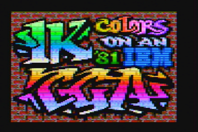
the folks who wrote "8088MPH" used this trick to create a low resolution 1024-color "mode" on the CGA card!
here's the demo if you've never seen it before. you should go watch it now if you haven't.
and here's the behind-the-scenes discussing some of the tricks involved. https://trixter.oldskool.org/2015/04/07/8088-mph-we-break-all-your-emulators/
quite surprisingly, it's also possible to display full motion video on an 8088 at 4.77MHz using a CGA card. in color. blows me away whenever i watch it.
CGA can't do color cycling oh wait what
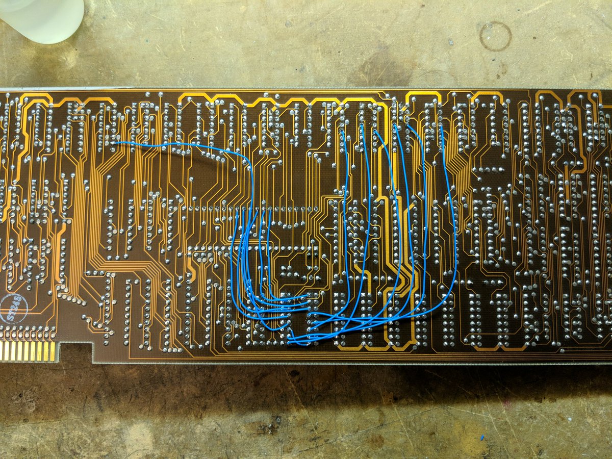
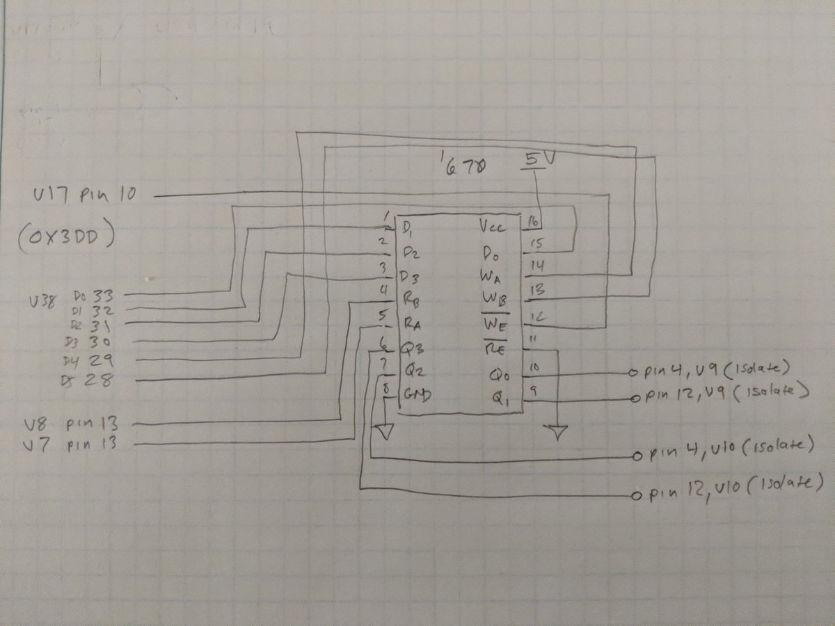
if you want to build this mod, this is the schematic. "isolate" means you have to disconnect those IC pins from the original circuit and connect them to the mod wiring instead.
so how does it end up working? to change a palette register, write a value to 0x3DD. bits 4-5 is the CGA color attribute to change, bit 0 is red, bit 1 is green, bit 2 is blue, and bit 3 is intensity.
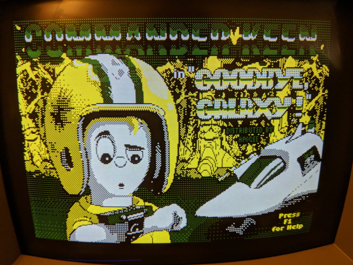
sadly you can't change attribute 0, that's always black since that color is generated in hardware. but the other 3 are fair game.
OUT &H3DD, &H19
OUT &H3DD, &H2A
OUT &H3DD, &H3C
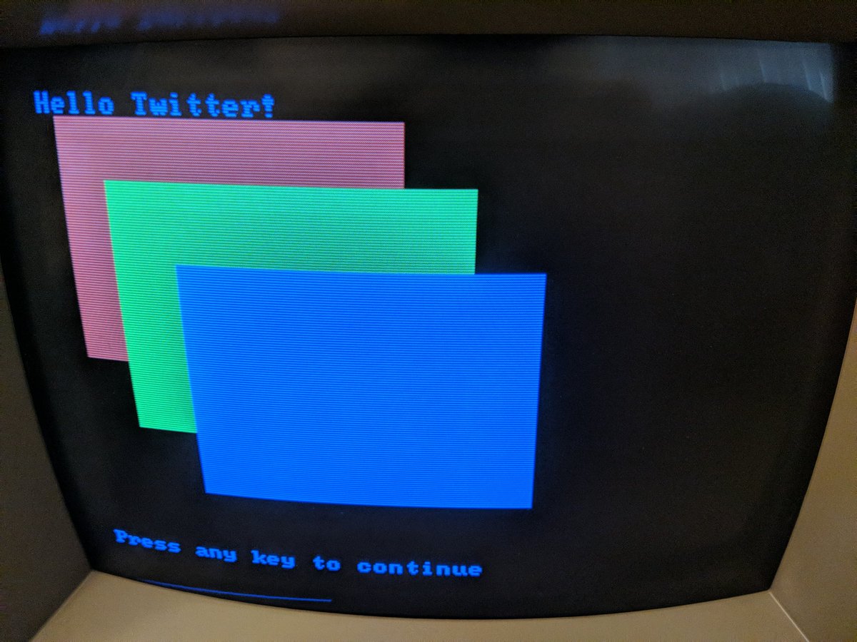
will give you a palette of bright red, bright green, and bright blue.
OUT &H3DD, &H19
OUT &H3DD, &H2A
OUT &H3DD, &H3C
will give you a palette of bright red, bright green, and bright blue.

 Read on Twitter