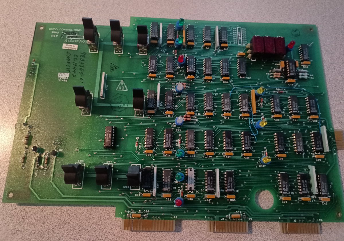
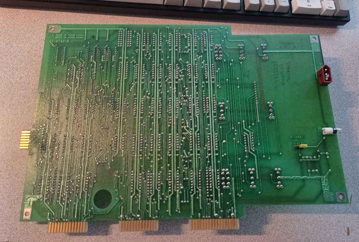
This is the front panel from the National Semiconductor C1700 Datachecker 1730. https://twitter.com/Foone/status/1344810609204838401
I was thinking they might have a small microcontroller on this somewhere but nope, it seems to pretty much all be 74-series logic
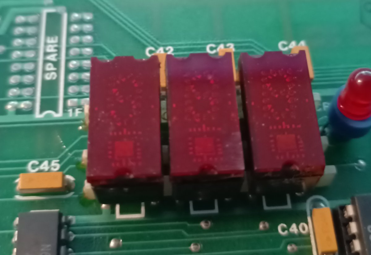
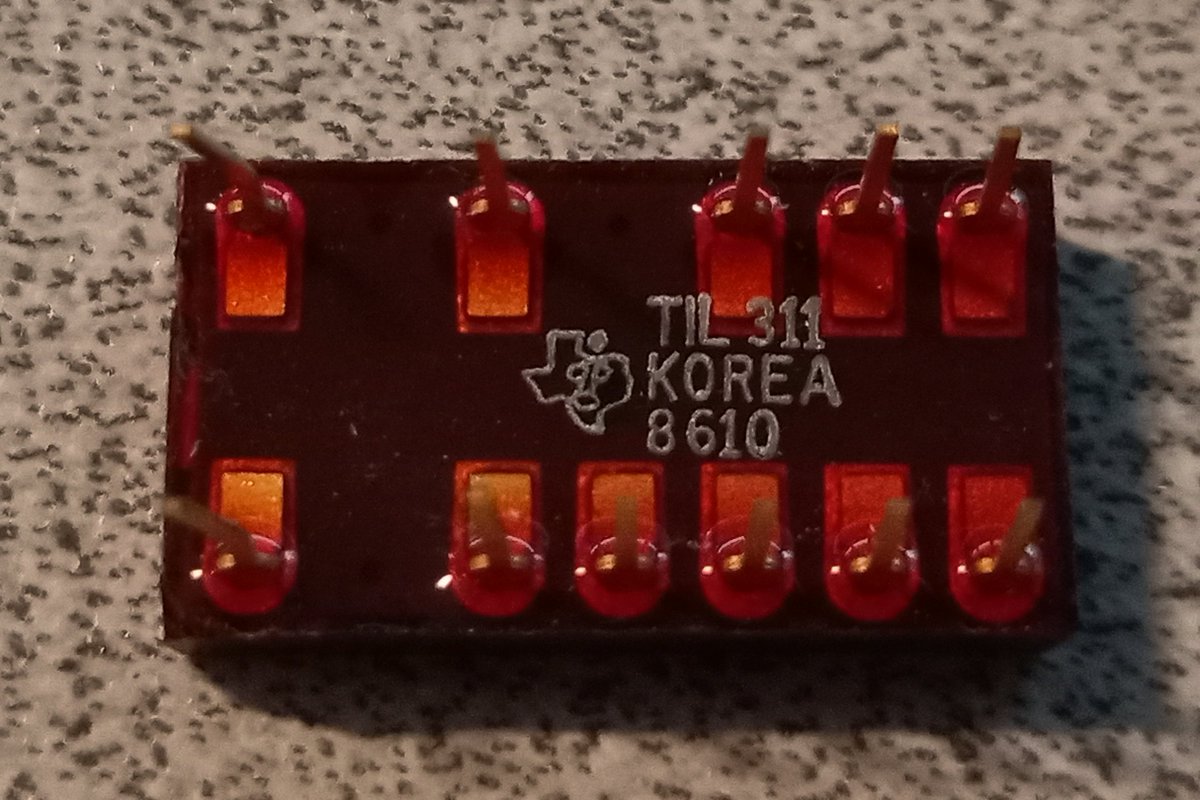
These 7-segment displays are odd looking. I wonder if that square at the bottom means they've got a chip on them? like a decoder?
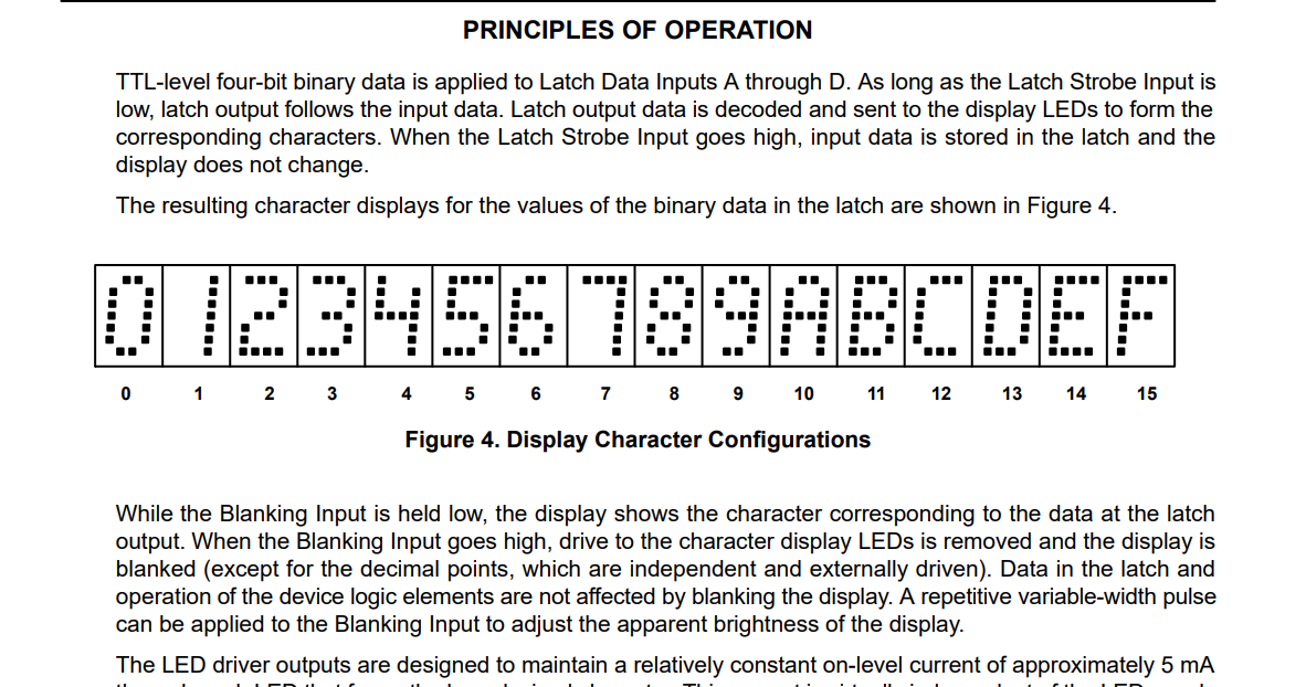
oh yeah, it's smart. It's a hex display with built in latch and decoder. So you can feed this 4 bits directly and it'll display the hexadecimal for it
Wired up an arduino sketch. Yep, looks cool!
I wired a button up to the strobe.
When the strobe pin is low, the data lines control the digits, but when it's high, the display uses the last stored value.
When the strobe pin is low, the data lines control the digits, but when it's high, the display uses the last stored value.
The actual contrast doesn't show up very well on camera.
Here's a quick edit to better show how it looks to the naked eye
Here's a quick edit to better show how it looks to the naked eye
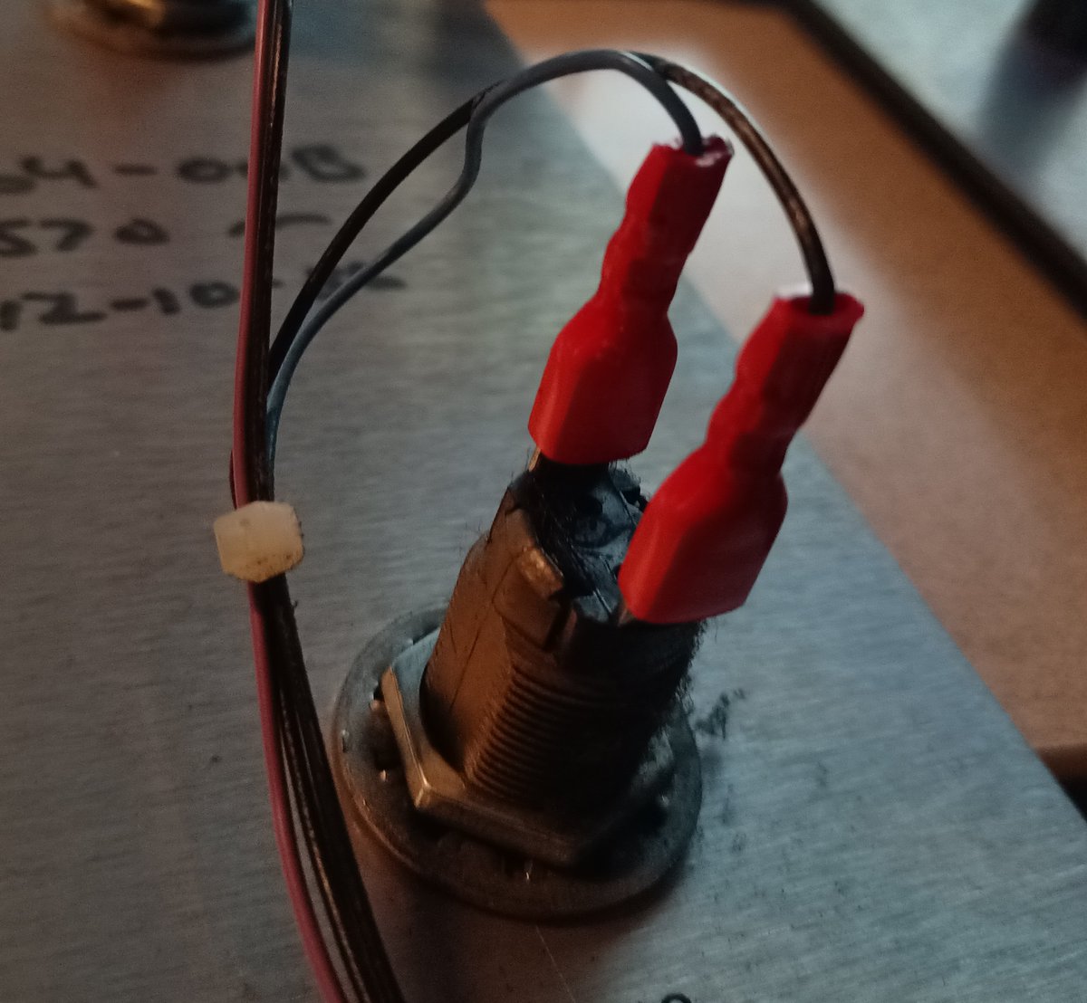
So, the two keyswitches have "EL101" and "EL102" printed on them.
Googling that , there is a key which uses that bitting system, it's the Hudson/Stanley EL101-EL359 series.
Googling that , there is a key which uses that bitting system, it's the Hudson/Stanley EL101-EL359 series.
So for about 18$ + shipping I can get replacement keys. I'm gonna wait on that though, because I'm not remotely near a state where I'm gonna power this thing on.
speaking of power... I took some more pictures of the power supply.
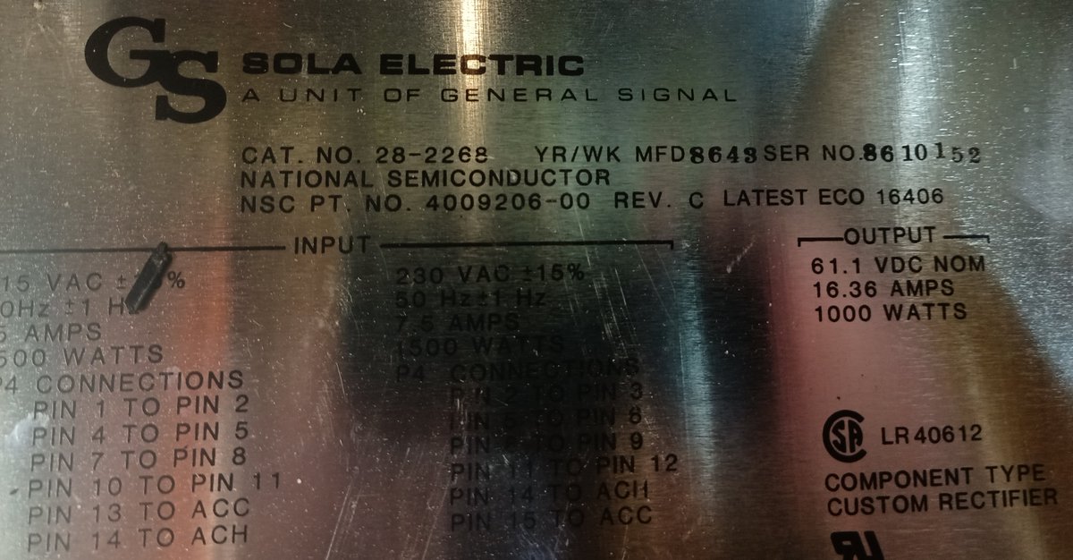
The first power supply (which is the second part of the power distribution system) is this, a General Signal/Sola Electric 28-2268.
It takes in AC power and produces 61.1 volts DC, at 16.36 amps.
The first power supply (which is the second part of the power distribution system) is this, a General Signal/Sola Electric 28-2268.
It takes in AC power and produces 61.1 volts DC, at 16.36 amps.
There's two of these, for redundancy.
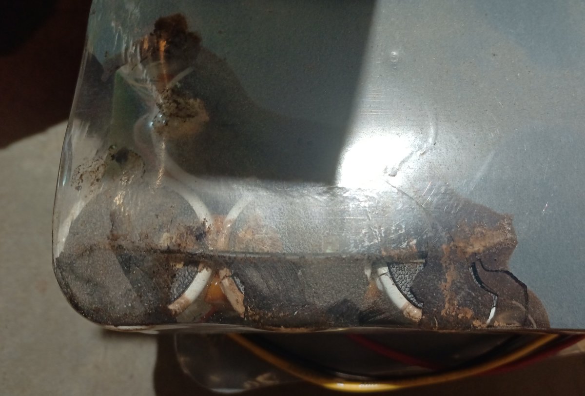
Both of them got damaged in the trip to my storage unit, sadly.
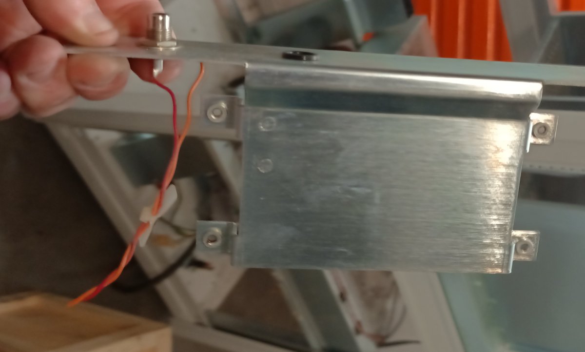
The little holder for the fuse got crushed.
Both of them got damaged in the trip to my storage unit, sadly.
The little holder for the fuse got crushed.
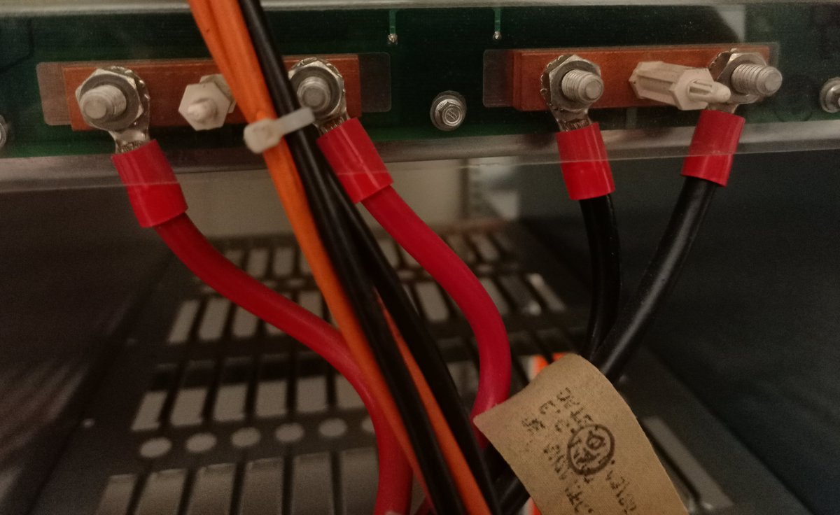
So the next phase (err, stage?) in the power supply system is this thing.
Well, both these things: it's duplicated again.
Well, both these things: it's duplicated again.
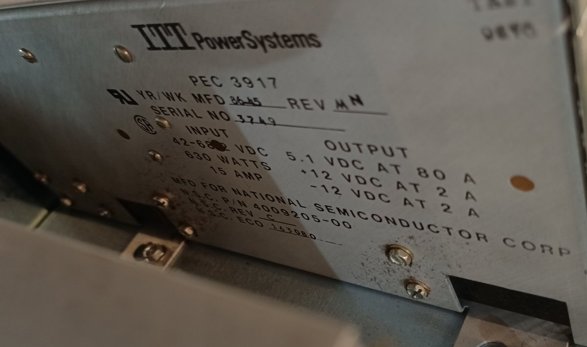
These are apparently custom-made for National Semiconductor by ITT PowerSystems.
They take in 42-68 volts DC and convert it to the three voltages the computer uses:
5.1v at 80 amps
+12v at 2 amps
-12v at 2 amps
They take in 42-68 volts DC and convert it to the three voltages the computer uses:
5.1v at 80 amps
+12v at 2 amps
-12v at 2 amps
This is pretty much the same voltages as a modern ATX power supply, just with 5.1v instead of 5v. (and I doubt the difference matters)
The 80 amps of +5v is quite high, though.
The 80 amps of +5v is quite high, though.
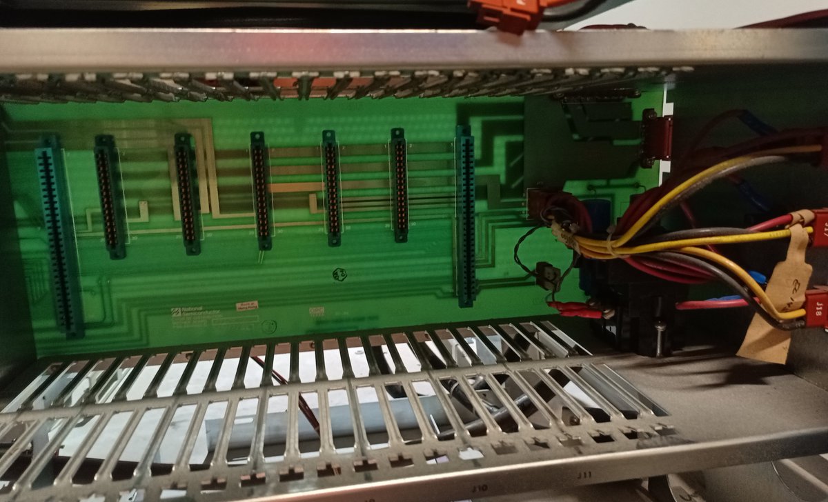
it turns out each of the backplanes has a little 3-pin connector for the -12v and +12v, helpfully marked on the PCB
So... I found this, on the IO box.
A customer number (361121002), options: J=2, K=0, L=2, M=2, disk: N=3, O=3, P=2, and I/O: Q=1, R=7, S=3, T=1.
A customer number (361121002), options: J=2, K=0, L=2, M=2, disk: N=3, O=3, P=2, and I/O: Q=1, R=7, S=3, T=1.
R might be "registers". Given the size of the store, 7 registers would make sense.
T... terminals? one terminal for controlling it?
T... terminals? one terminal for controlling it?
So inside the I/O box, we've got this.
Apparently everything: registers, terminals, and whatever else!) is permanently hardwired into the system. There's no connectors.
And this was uninstalled using hedge trimmers.
Apparently everything: registers, terminals, and whatever else!) is permanently hardwired into the system. There's no connectors.
And this was uninstalled using hedge trimmers.
This has four modular boards installed.
Each cable has up to 16 conductors in it, with different numbers being connected for different cables.
Each cable has up to 16 conductors in it, with different numbers being connected for different cables.
It's hard to see in the pictures, but there's also a single RCA jack here, which is two-conductor ("mono", if it was audio)
it turns out that goes nowhere.
This is one of the cables we had to cut to get this thing out of the place it was stored, and I believe this goes to a small fan? I'll have to confirm when I'm putting this all back together.
This is one of the cables we had to cut to get this thing out of the place it was stored, and I believe this goes to a small fan? I'll have to confirm when I'm putting this all back together.
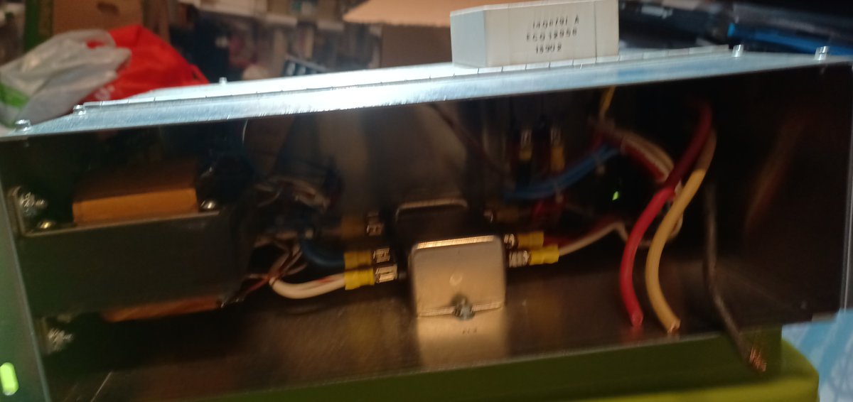
So, there's also a stage-zero of the power supply. This is where the main switch is, and where the power cables came in.
You can see here, they were cut off.
You can see here, they were cut off.
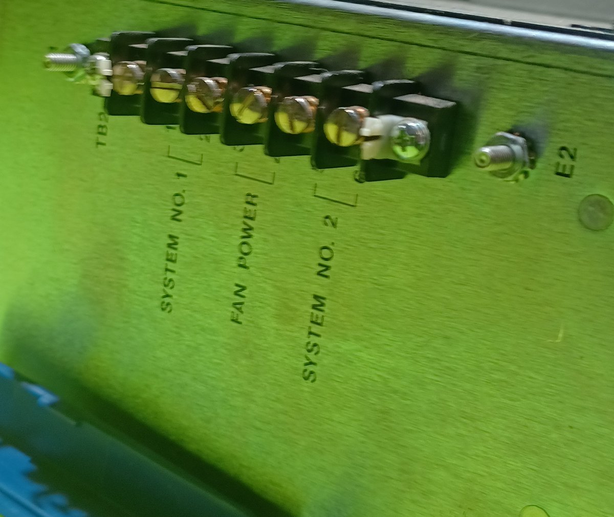
This has connectors on the side which go to each of the two stage-1 power supplies, as well as separate connections for fan power.
There's also switches on the front (the pictures didn't come out, sadly) for switching each half on/off.
There's also switches on the front (the pictures didn't come out, sadly) for switching each half on/off.
So, it turns out this thing has up FOUR backplanes.
Two duplicated ones for the main computer cards, a set of analog boards connected to the front panel (which I don't think I have pictures of yet), and these down here
Two duplicated ones for the main computer cards, a set of analog boards connected to the front panel (which I don't think I have pictures of yet), and these down here
It turns out, these are part of the power system!
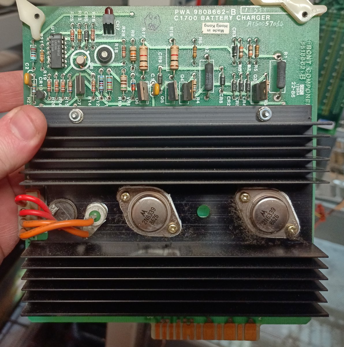
This one is a battery charger. There's two of these, one for each battery.
This one is a battery charger. There's two of these, one for each battery.
Then there's this, the Supervisory BD.
I'm guessing this is used to monitor and switch power sources?
I'm guessing this is used to monitor and switch power sources?
Here's the inside of the power supply-backplane box, with the cards pulled out.
I think that's a big relay (or two) back there? presumably to switch the two power supplies off and on if needed.
I think that's a big relay (or two) back there? presumably to switch the two power supplies off and on if needed.
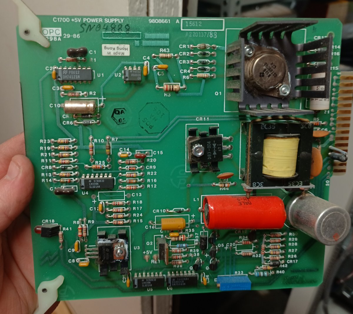
I'm not really sure why there are +5v cards in here. The fans are powered separately from the stage-zero power supply, and the two computers have their +5v coming from the stage-2 supplies.
What is this +5v for? the aux/supervisor boards?
What is this +5v for? the aux/supervisor boards?
ANYWAY the power plan is still: make my own power supply rather than use any of these.
They're neat but they're also up to 36 years old and have lots of huge capacitors.
They're neat but they're also up to 36 years old and have lots of huge capacitors.
I'm far from being at the point where I'm even considering powering up any of this system, though, so that's not really a worry yet.
The next part I need to disassemble and take pictures of is the analog boards, which were connected directly to the front panel.
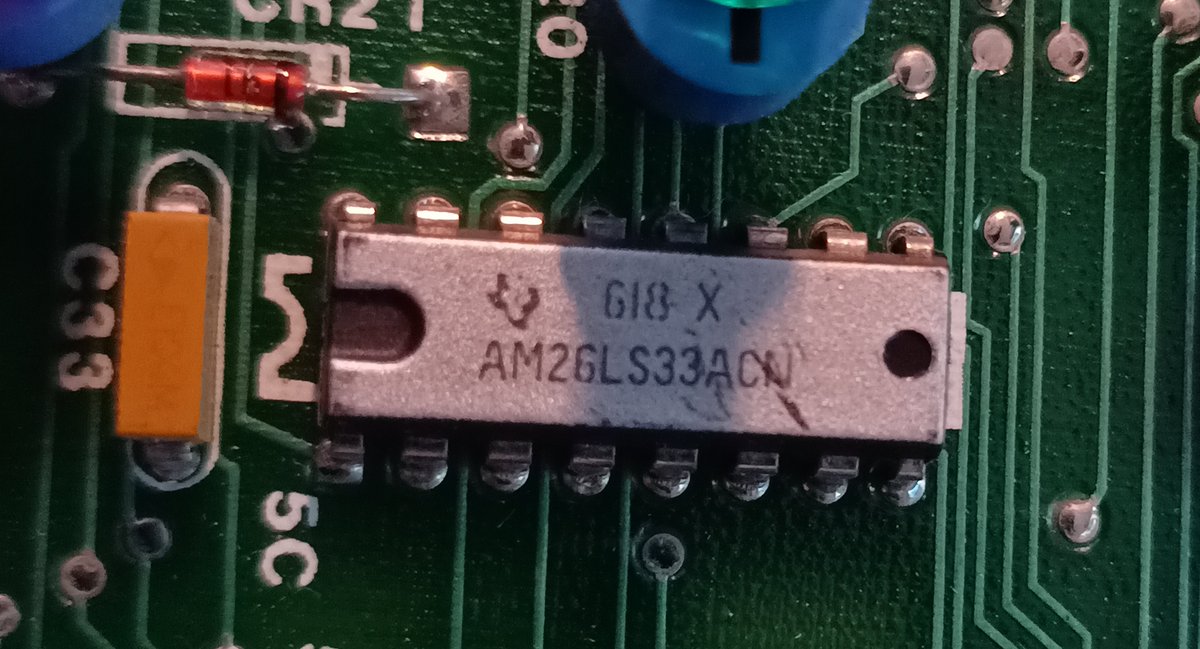
I'll also need to dump all the eproms on the assorted computer boards. Maybe document how this front panel works. It has the same transceiver chip as the other parts, maybe I can use it to figure out how the communications works.
then I gotta look into dumping the 8" floppy disks and the two SMD hard drives.
that's SMD as in Storage Module Drive, the protocol invented by Control Data Corporation in 1973, not Surface Mount Device.
Anyway, if you look at the back of the key-switches you can tell that they would be trivial to hotwire. So I really didn't NEED to pick it open, that was just for fun.
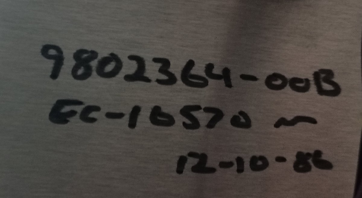
BTW, this is on the front panel.
I was told "EC-16570" was the installation code, and probably also the password to the OS.
12-10-86 is the install date, apparently.
I was told "EC-16570" was the installation code, and probably also the password to the OS.
12-10-86 is the install date, apparently.
Here's the back of the front panel, with the PCB removed.
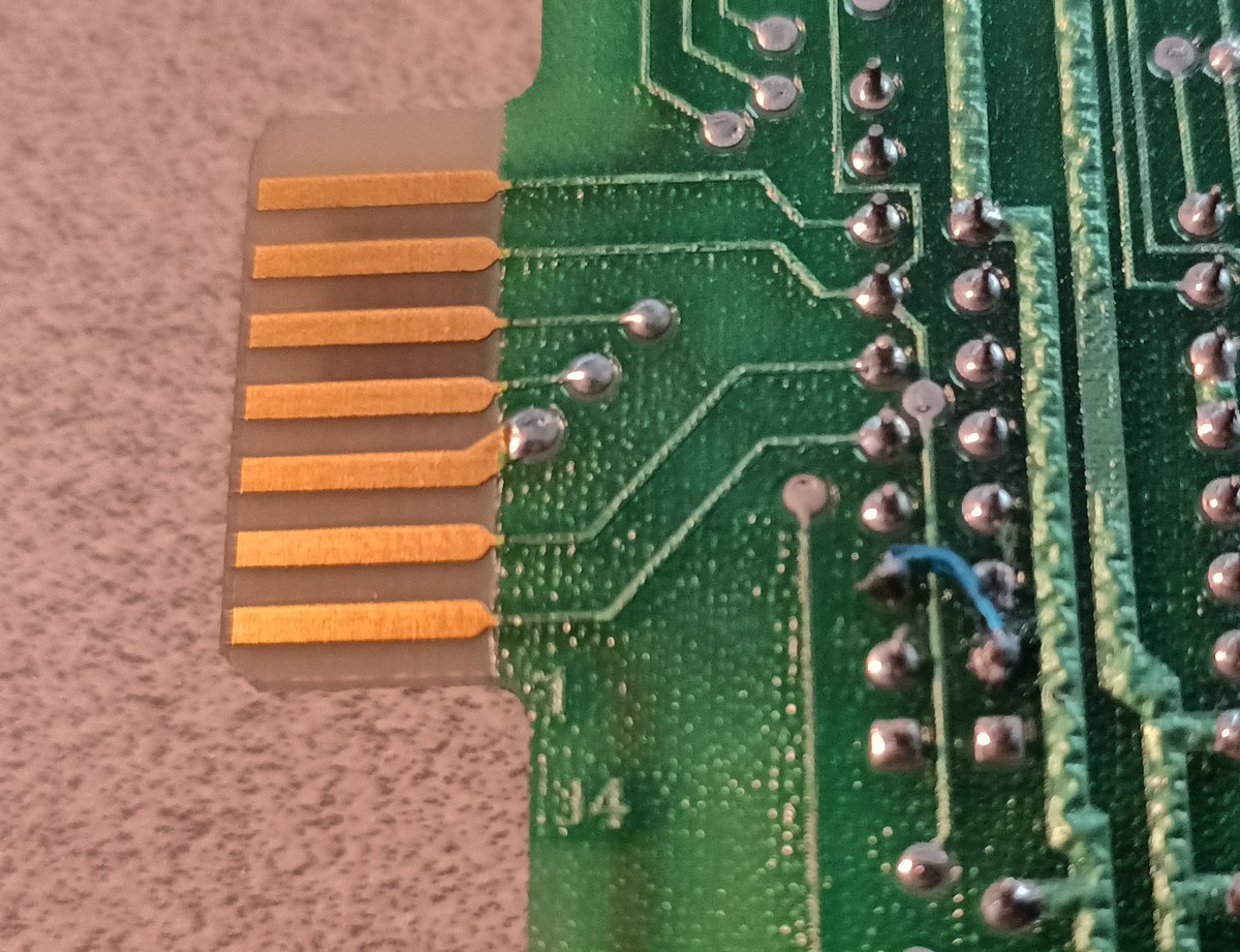
The two keyswitches and several buttons are all connected together, to a card-edge connector.
(one of them had to be undone to get the PCB out)
The two keyswitches and several buttons are all connected together, to a card-edge connector.
(one of them had to be undone to get the PCB out)
The only info I've seen so far about how to get data off an SMD drive is this interesting project by Chris Fenton which uses an FPGA and some parts from a 3D printer to manually move the head of the drive while capturing the raw data at high resolution:
https://www.chrisfenton.com/cray-1-digital-archeology/
https://www.chrisfenton.com/cray-1-digital-archeology/

 Read on Twitter
![It's been [0] days since I've had to lockpick a computer on It's been [0] days since I've had to lockpick a computer on](https://pbs.twimg.com/media/Eq10hA5UUAArZIg.jpg)
