Part 4 of #CivEngExplained How Bridges Work – Bearings and expansion joints. This one is all about movement; which generally you never think a bridge should move, unless it’s a lifting or swing bridge; but I’m not talking about those tonight. Or transporter bridges.
Parts 1-3 available here if you missed them:
Part 1 Introduction to Bridges: https://twitter.com/russiankiwi3/status/1343638897729949697?s=20
Part 2 Foundations: https://twitter.com/russiankiwi3/status/1343979691443712006?s=20
Part 3 Deck Construction and Deconstruction: https://twitter.com/russiankiwi3/status/1344311711441055745?s=20
#construction #bridges #civilengineering
I’ve touched on why bridges move and need to move, and the difference between integral and non-integral bridges, as well as different construction materials such as concrete and steel beams, which also affect movement. We’re going to look at this in much more detail tonight.
Remember the forces I explained in Part 2? They are generally present in every bridge, depending on type and construction. Some bridge designs will introduce extra forces, which means more movement in more directions. Let's look in more detail:
We all know metal expands when it’s warm, and contracts when cooled. The concrete we use is reinforced with steel bars to manage tensile forces. So in summer months, the concrete expands. Believe it or not, concrete is fairly flexible!
When concrete cures it is like baking pastry in an oven. The outside dries first, and your pie gets a nice golden dome. But inside, the thicker pastry is softer. The concrete in the middle of sections will cure slower.
Also, pouring concrete can take hours or even days. So different parts of the structure are curing at different rates. We vibrate the air out, but tiny air bubbles, of a few millimetres or even less, remain.
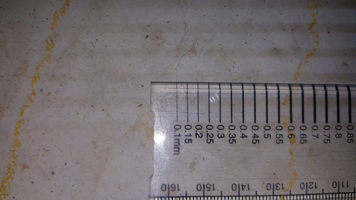
This difference in curing rates and tiny air bubbles lead to microscopic cracks forming, too small for the eye to see. These cracks allow the concrete to flex. Normally this would be bad, but the rebar holds all the concrete together despite the cracks.
So when the air temperature increases, the reinforcement bars and air trapped in the concrete expands, and the elements stretch. When it cools down, the sections shrink.
Of course, when steel beams are used, this effect is even more prevalent. Often the steel wants to expand more than the concrete allows, so the concrete restricts the movement. The shear studs between beams and concrete helps manage this.
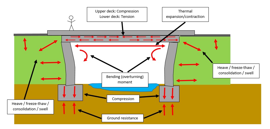
When the deck expands, it will push the abutments away from the deck centre; at a tiny scale, the abutments bend, as shown exaggerated in my sketch. If you actually saw concrete bend like that I'd be very worried!
Ground also expands and contracts, in wet or moist conditions, the ground heaves. When it dries, it shrinks – think of mud cracks in a dried-up puddle. When it expands, it pushes the abutments towards the centre of the deck.
Most of this movement is lateral i.e horizontal – decks getting longer & shorter, abutments moving inwards and outwards. But there can be vertical movement too.
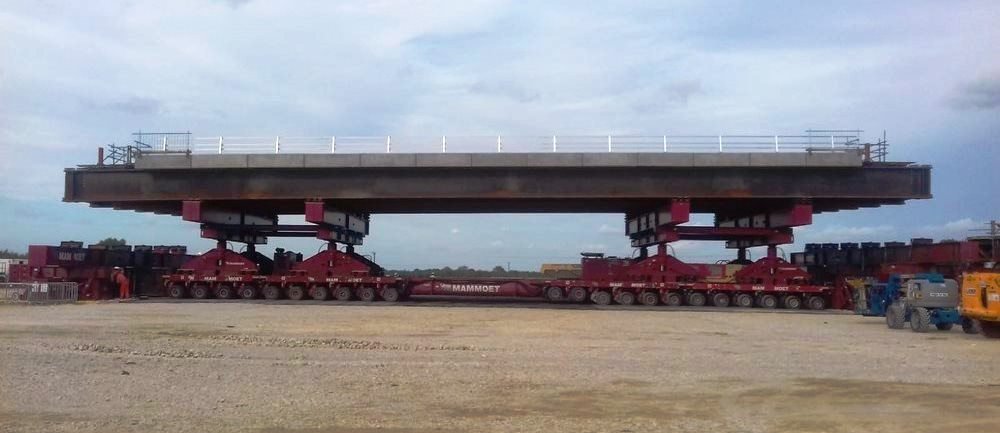
For bridges with multiple spans and piers, often the piers carry the bulk of the load. Imagine balancing a sheet of paper on an upright pencil – the ends of the paper will sag downwards. The same happens to a bridge deck if supported on a central pier.
When decks expand and contract, deck ends lift up/down. As vehicles pass over, it will flex & ‘bounce’. So vertical movement needs to be accounted for too.Other movement such as settlement of supports & vehicle strike introduce forces into the structure and may need considering.
For relatively short spans of 30m, the movement is small enough that the concrete and steel can cope with these forces without resulting in damage to the bridge. An integral bridge has no movement joints and can manage the movement forces.
The reinforcement design within the concrete will be optimised to deal with these forces and allow the bridge to flex without causing damage. The Bar Hill bridges on the A14 have spans of 40m, with steel beams – but are integral! The concrete can cope with the expected movement.
However, with longer spans, the movement is increased. Left unchecked, the concrete would break up, steel sections would rip and twist, cracks would let water in, cause rust, lead to further damage, and eventually the bridge would fail.
So to prevent this, we separate the deck and abutments, and leave a gap for movement to occur, a space for the deck to expand and contract into. This is a non-integral bridge. You can have on or multiple movement joints in a bridge.
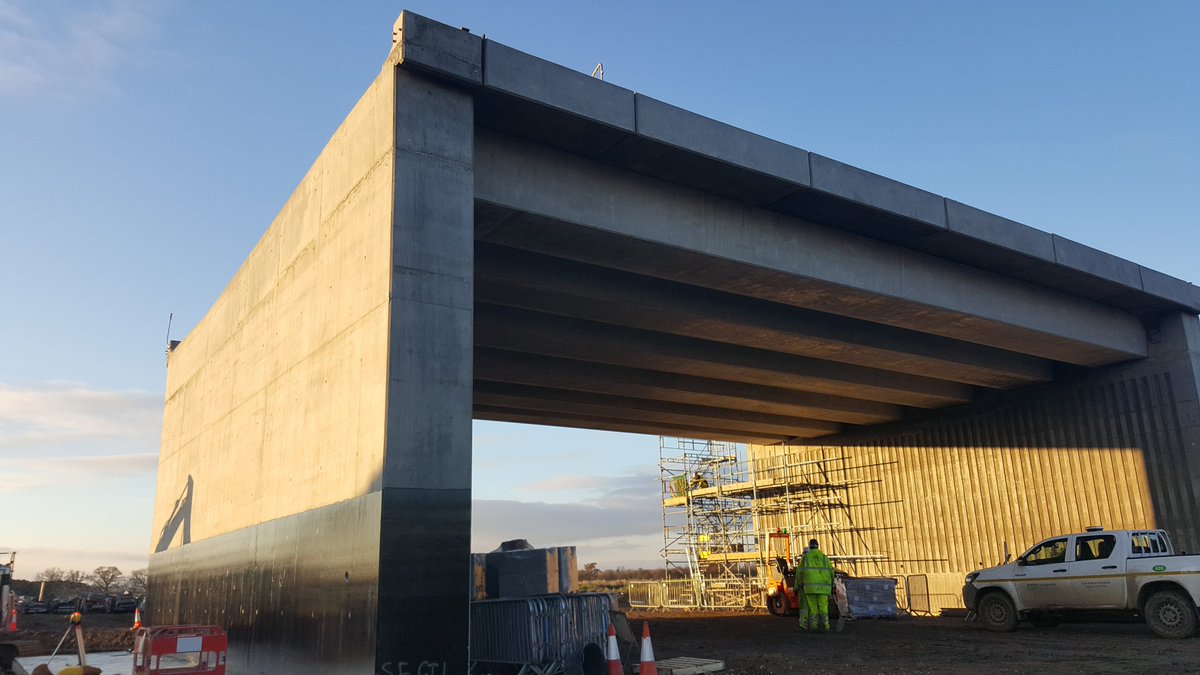
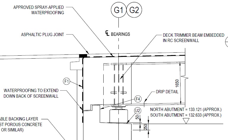
How do we separate the deck and abutments? They become physically separate concrete sections; and the deck sits on the abutments using bearings. Bearings connect the deck to abutments, transfer the loads, and allow movement. Photo 2 shows gap between deck & abutment from below
Bearings come in various types depending on the bridge. I’m going to use the Luton Road overbridge at the M1 J11a as a first example as it has several types. Different types control which way the movement occurs, so the bridge behaves as designers planned.
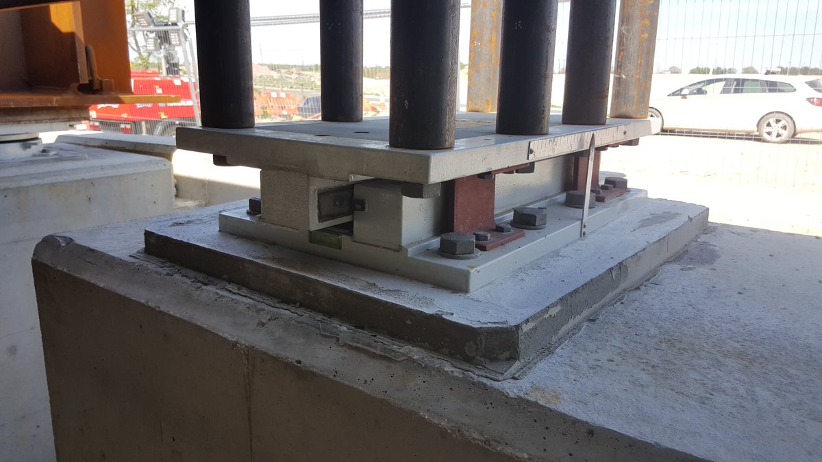
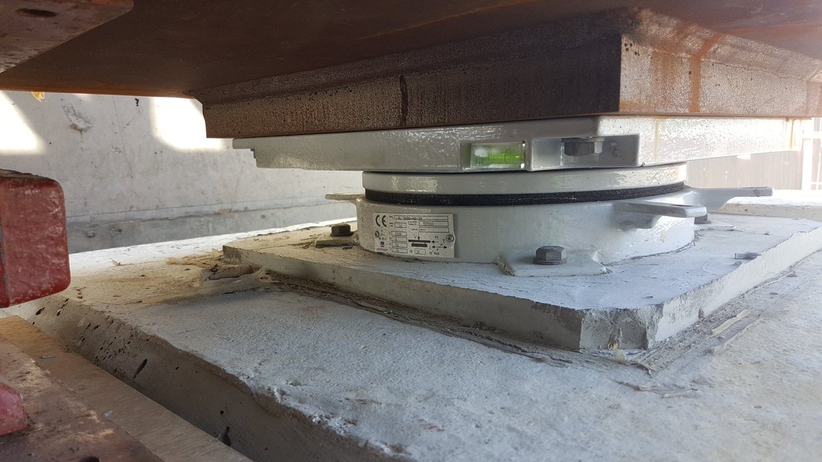
First, the fixed bearing – this allows no movement. The deck is pinned to the abutment or pier at this location and no movement can occur. The bearing is on the abutment, and the steel beams of the deck are fixed to the top of the bearing in this photo.
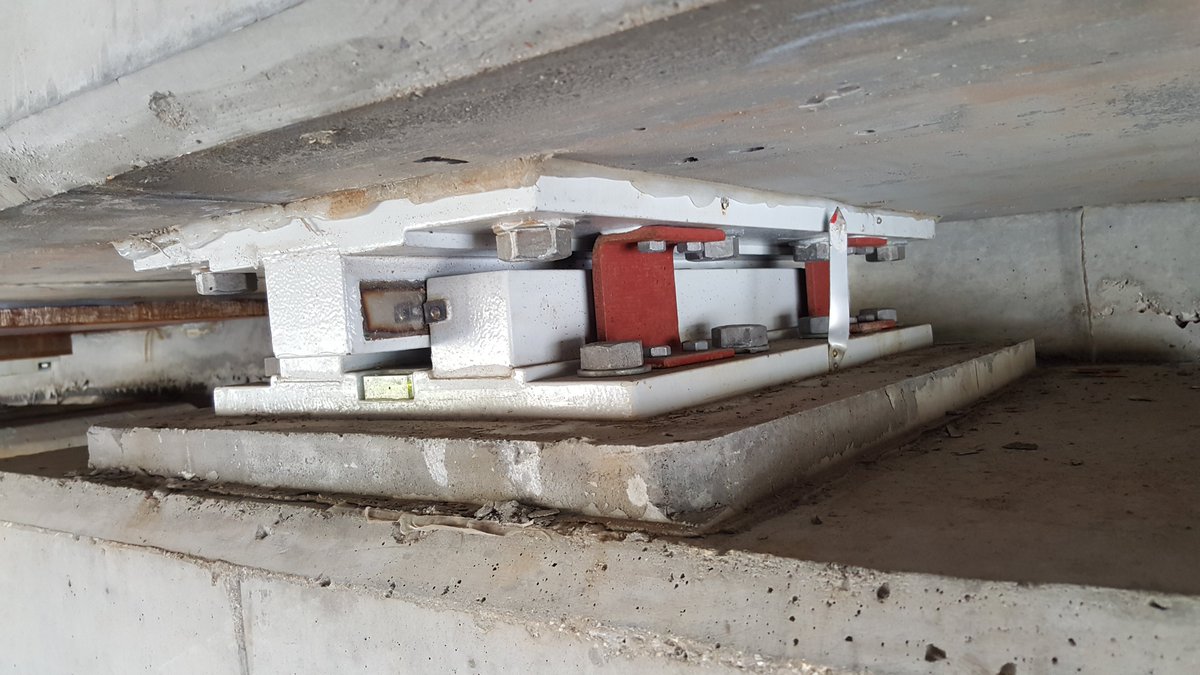
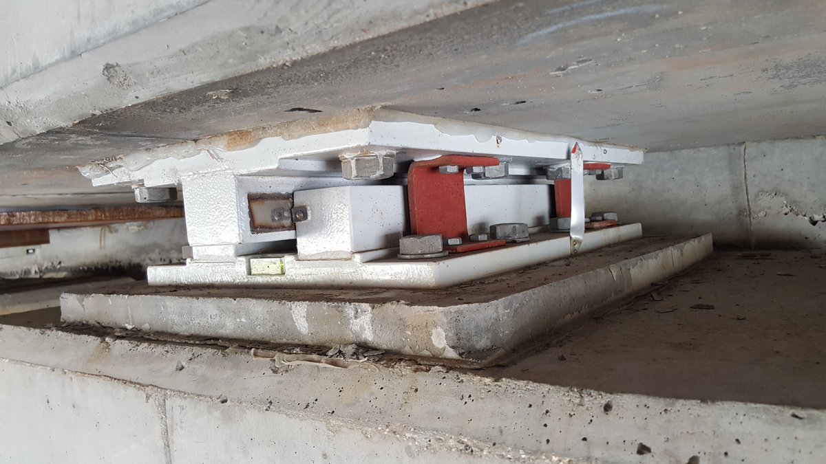
Next, the sliding bearing. This has two plates that slide past each other, allowing movement in one axis only. This is generally used along the centrelines for equal movement, and keeps the bridge centred as it moves. There is a ruler with centreline to measure movement.
Then, the free-movement bearing. This allows movement in all directions. All of these can also permit or restrict vertical movement, depending on the requirements.
The fixed and free-movement bearings used here are called pot bearings. The feature an elastomer layer encased in steel. The weight of the bridge is so much that the pressure turns the rubber into a liquid, which allows the movement.
The sliding bearings are literally a steel nib fixed to the deck, sat within a groove fixed to the abutment (or vice versa). They have spirit bubbles fitted to ensure they are level in order to work correctly.
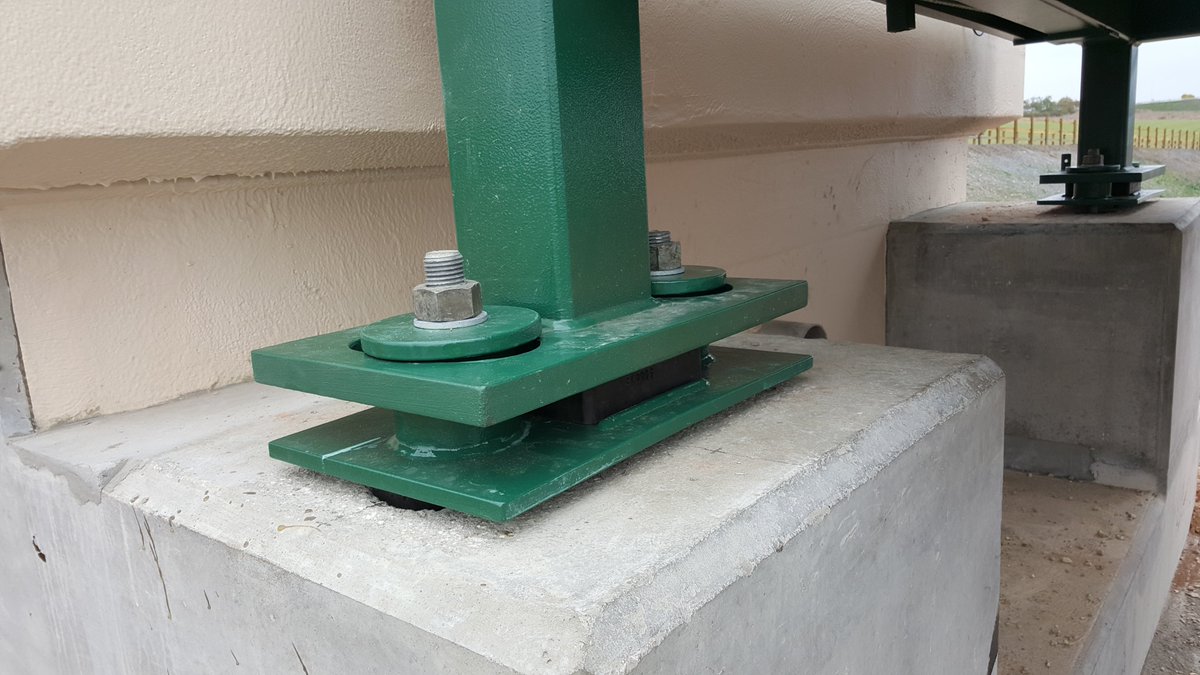
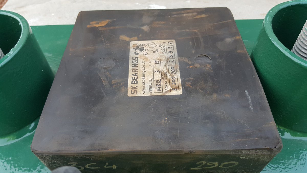
Elastomeric bearings are made of engineered rubber, sometimes with steel plates built in. Here they are being used to support a metal footbridge. These are just rubber pads and so don't restrict movement at all - they are free-range bearings.
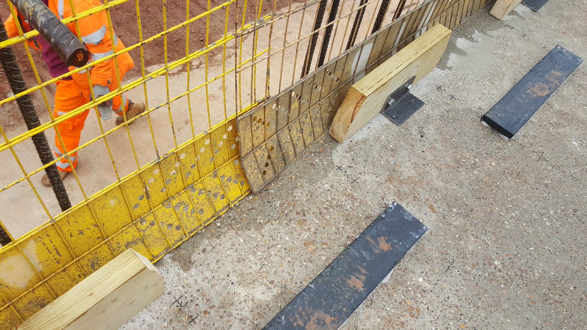
Temporary bearings are sometimes used to help land bridge beams in integral bridges – these can be simple rubber strips, nylon shims, or a stub of metal. These are temporary and have no effect on the operation of the structure once the abutments are cast.
Wherever the deck is pinned, whether midway along the span or at one end, the other bearings must allow movement away from the fixed bearing. Alternatively, completely free movement is allowed and the deck kept in place by concrete guides.
So – we’ve built a long bridge with steel beams, determined the movement is sufficient to require bearings – how do we get the road onto the bridge whilst providing this movement? Asphalt is flexible, but only to a point.
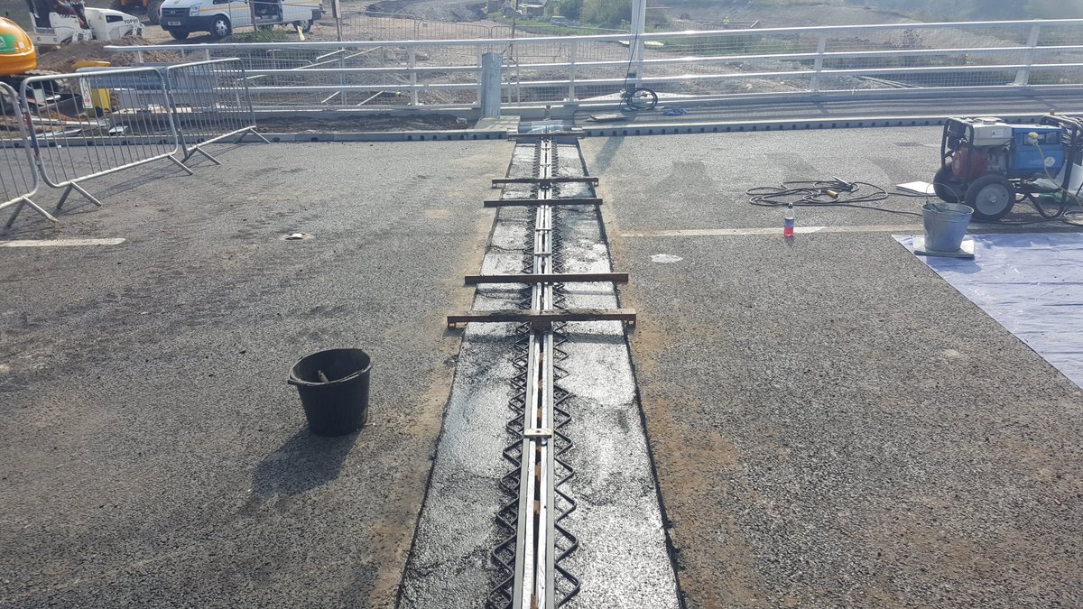
This where expansion joints come in. The term can refer to any gap for movement, but we’re going to look at carriageway joints i.e the roadway. Like bearings, different types allow for different movement ranges.
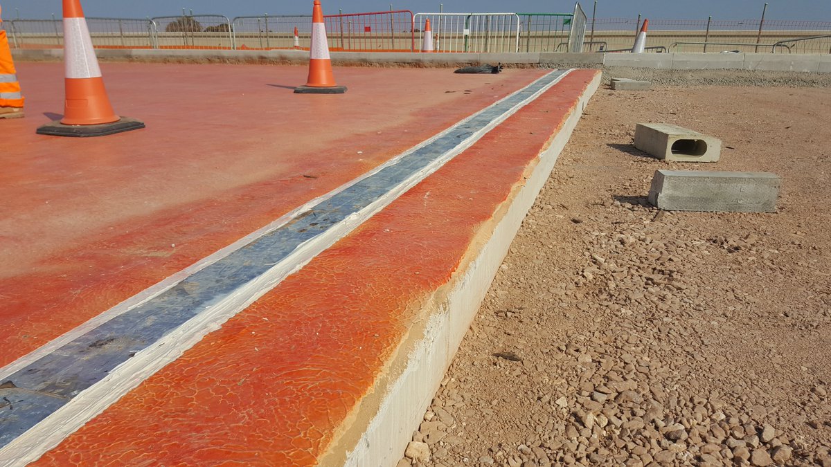
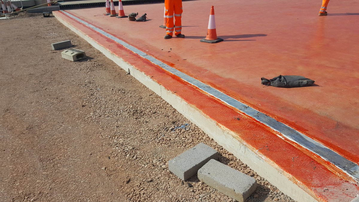
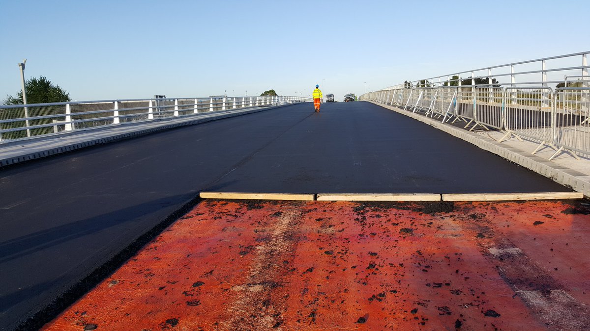
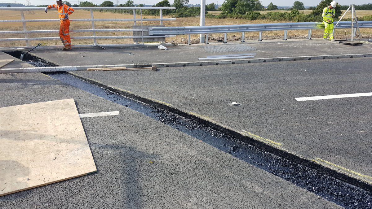
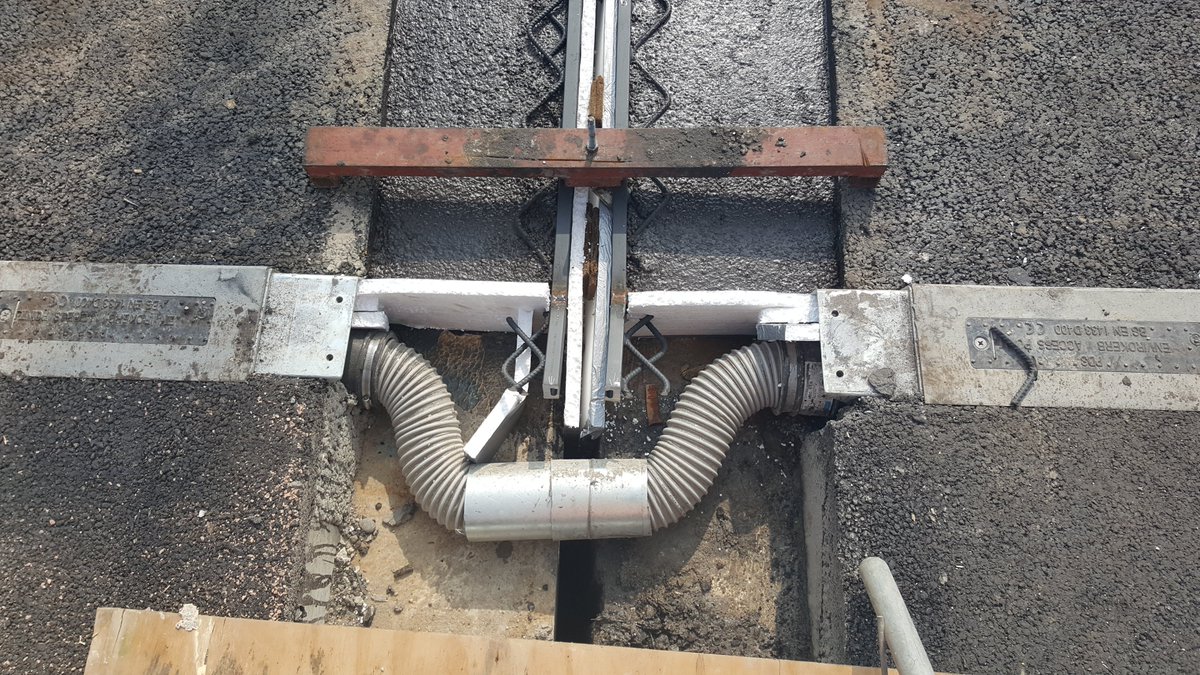
The simplest type is a buried joint. A metal or rubber plate bridges the gap from abutment to deck, the asphalt surfacing laid, and then a cut is made in the road. The cut is sealed with bitumen, and this is flexible enough. The metal plate is shown in these photos.
This is generally good for movement ranges of around ±10mm. It’s simple and low-maintenance. It is also used on integral bridges, as I said earlier integral bridges will still have some movement. The red stuff is bond coat, which helps asphalt stick to the deck.
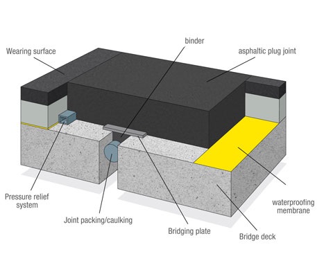
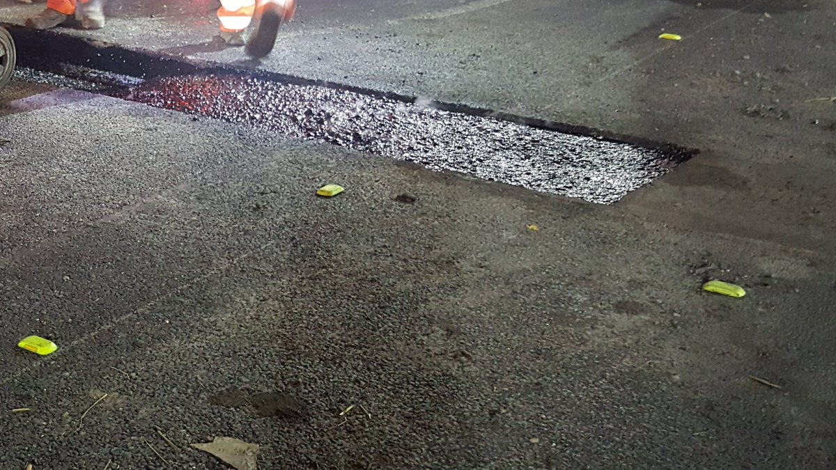
The next type of joint is the asphalt plug joint (APJ), for horizontal movement of ±25mm and ±1.5mm vertically. It is a stone and bitumen mix, heated to high temperatures and poured into a trench within the road.
APJs are installed at around 200 degrees. They cool within a few hours, and are topped off with an anti-skid coating. They are watertight and very commonly used on integral and non-integral bridges.
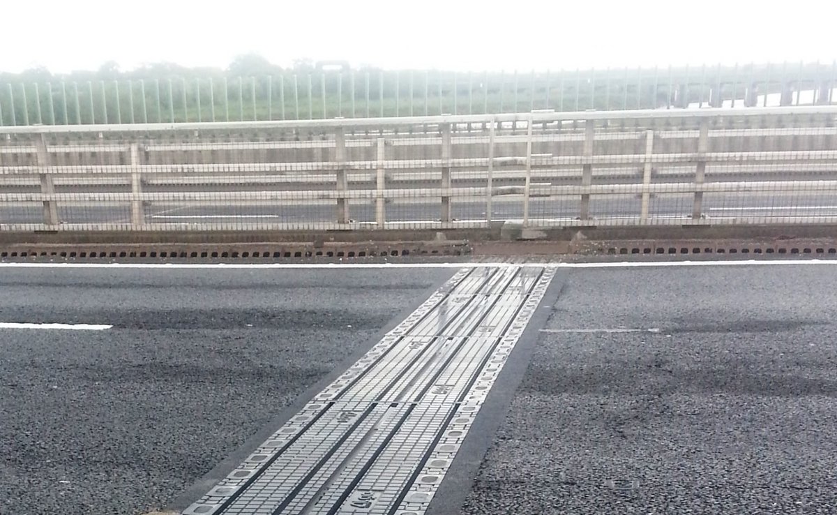
Rail joint; a flexible rubber/plastic strip spanning the gap, gripped by steel rails set into the road. Different cross-sections exist depending on manufacturer but the principle is the same. Used on non-integral bridges for approx ± 75mm movement.
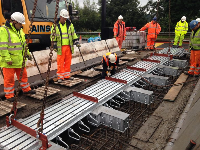
Then we get into the really big joints – alligator teeth/finger joints, transflex plates etc – basically overlapping or sliding sections that span the movement gaps. The biggest are reserved for huge bridges such as suspension bridges.
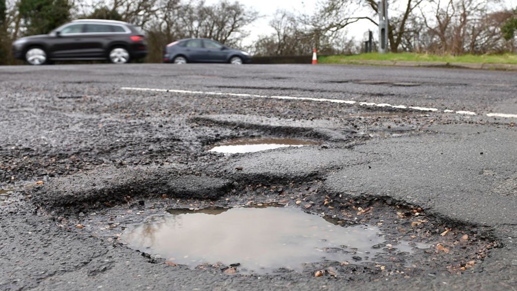
Joints usually have a lifespan of 25 years. However, they are a weak point. They get battered by thousands of vehicles each day, are exposed, get salt & oil washing over them, and are costly to replace. The same goes for bearings.
There is a growing shift to purely integral bridges, as they are cheaper to maintain with no bearings or expansion joints. But we are also building longer bridges, so bearings and joints will remain features of bridges for a while yet.
That's it for Part 4, I hope you have found it interesting. Tomorrow we round off with wingwalls, waterproofing and a select few 'other bits'! Enjoy your evening and #HappyNewYear
Image credits:
Pot bearing diagram: https://www.steelconstruction.info/Bridge_articulation_and_bearing_specification
Pothole photo: https://images.app.goo.gl/k8hTV7qN4QUGAqmt9
Steel finger joints: https://freyssinet.co.uk/bridge-expansion-joints/
Plate joints: https://bridgejoints.org.uk/bridge-joints/
APJ Diagram: Stirling Lloyd/Thormajoint
#construction #civilengineering #bridge

 Read on Twitter