Good afternoon! If you need a distraction from 2020 doing its' best to twist the knife one last time before the year end, grap a cuppa, sit back and enjoy Part 3 of my #CivEngExplained series on 'How Bridges Work - Deck Construction and Deconstruction! #construction #Engineering
Missed Parts 1 and 2? Available here:
Part 1 - Introduction to Bridges: https://twitter.com/russiankiwi3/status/1343638897729949697?s=20
Part 2 - Foundations:
https://twitter.com/russiankiwi3/status/1343979691443712006?s=20
#bridge #civilenegineering #highways
Part 1 - Introduction to Bridges: https://twitter.com/russiankiwi3/status/1343638897729949697?s=20
Part 2 - Foundations:
https://twitter.com/russiankiwi3/status/1343979691443712006?s=20
#bridge #civilenegineering #highways
Part 2 discussed foundations, which are mostly below ground, and is known as the ‘substructure’. Everything above ground is the ‘superstructure’, such as wingwalls, abutments and deck. The deck is the section spanning between piers and abutments.
Before I launch into types of decks, firstly we’ll look at what influences deck designs. Yesterday I talked about the forces acting on bridges, and in particular the deck. Vehicle loading, thermal expansion & contraction, and wind are some examples.
Decks’ purpose is to support vehicles, pedestrians, trains, boats etc that the bridge is being built for. Remember from Part 2 – Pressure = force/area. Therefore a narrower footprint gives a higher pressure. Vehicle tyres are quite narrow & exert precise ‘point’ loads on decks.
For roads, expected vehicle loadings are referred to as ‘axle loads’ & is the maximum expected loading. This isn’t just a fully-laden lorry; sometimes bridges are on designated ‘heavy-haulage’ routes for abnormal loads and so need higher bearing capacities.
Trains distribute loads better but rail vehicles are much heavier than road vehicles. Trains exert bigger forces on bridges under braking which also needs to be taken into account. Tall bridges often have major wind loads to consider.
Decks are one of the most exposed parts of bridges. I’ve previously explained what can happen when things go wrong, on the A52 Clifton Bridge in Nottingham in this example: https://twitter.com/russiankiwi3/status/1226188705095876608?s=20
Brake dust, oil & diesel, de-icing salts and chemicals, and salt water if in a marine environment, all attack the concrete & steel, cause degradation and corrosion. If left long enough, this corrosion can cause the structure to fail.
Therefore the deck design needs to withstand potential corrosion & degradation. The deck needs to connect to the abutments, which may have a specific design due to the ground conditions; this may also affect the deck design.
The geometry of the bridge also affects the design. Are we building a sweeping curved slip-road? Is it an 8-lane motorway? Are we spanning a wide valley? There are loads of factors that go into creating the design.
Another major factor is how is the bridge going to be built? In the UK the designer is required by law to consider how the bridge will be built. Lots of projects involve the contractor at design stage to help influence the design.
Offline construction; building away from the main infrastructure e.g building a bridge in a field. This is the best and easiest form; no other cars or trains to deal with, less people & neighbours, more space to build.
Online construction; building a bridge over/under the road or rail line, generally more complex than offline builds but also very common. Sometimes we are altering or rebuilding existing structures, very popular on rail schemes.
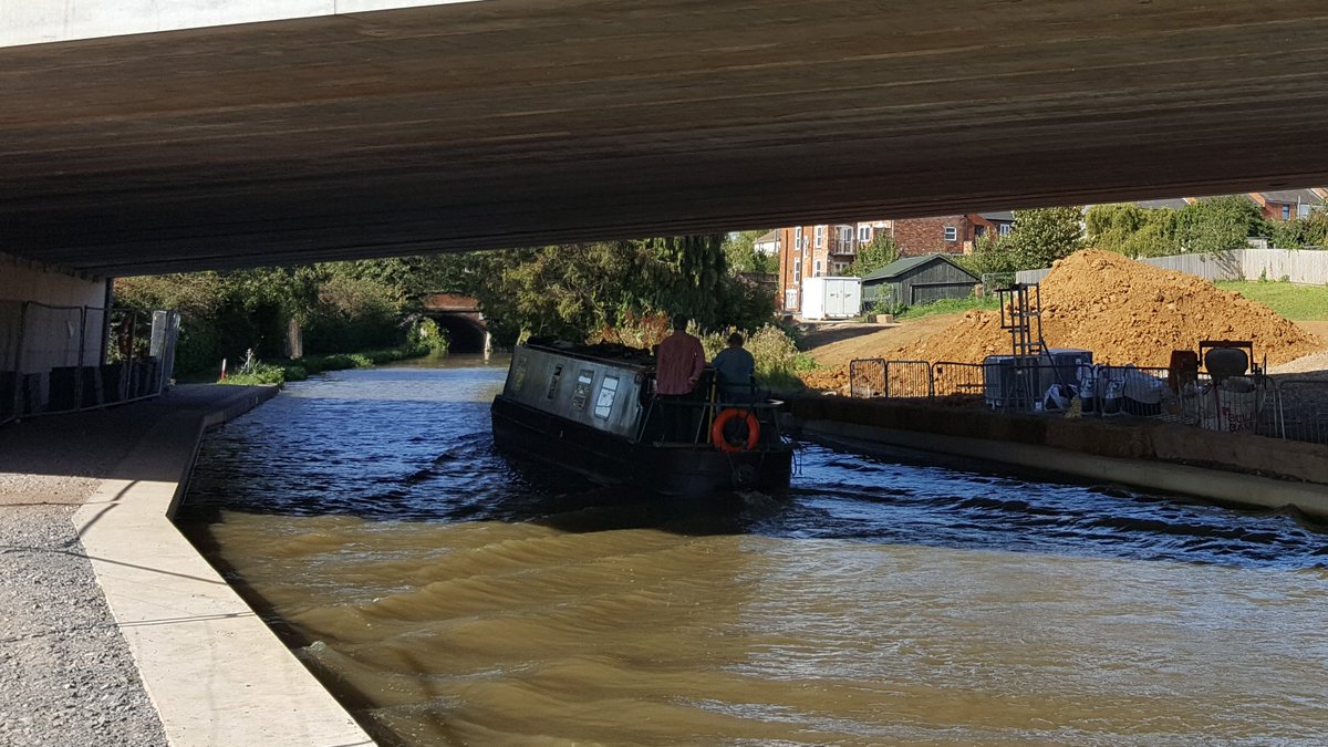
For offline bridges, multiple designs and methods are available as you have the time & space to do lots of things. Canals and rivers generally count as ‘offline’ as they are far less onerous to deal with; canal boaters are friendlier than 8 lanes of commuters!
Online bridges have more constraints; you may have to keep 6 lanes of traffic moving, or only be allowed to work on the rail line for 4 hours a night except Bank Holidays. Public safety & minimising disruption is priority.
As always I’m only skimming the tip of a huge bridge-design iceberg, and I don’t want to overstep and be mobbed by hordes of angry consultants. So, tea-break over – time to look at types of deck.
The oldest bridges were brick or blockwork arches; sometimes multiple arches into viaducts. There may be several brickwork leaves with a stone or rubble core. The arches were topped with stone and the road/rail line built on top.
These bridges are great, some Roman arches have stood for thousands of years. But blockwork is limited in span widths; and today we want to span bigger and bigger gaps. Arches were great for rail as rail lines have a narrow cross-section.
With the exception of canal, river and rail bridges, most of our road bridges were built in the 20th Century – the UK’s road network is relatively young compared to some of our infrastructure. Most concrete bridges will be around 50-60 years old when major roadbuilding happened.
So most of our bypasses and motorways were brand-new construction, and featured lots of bridges. Bridges keep things separate and free-flowing, they made things safer, allowed higher speeds, and looked good!
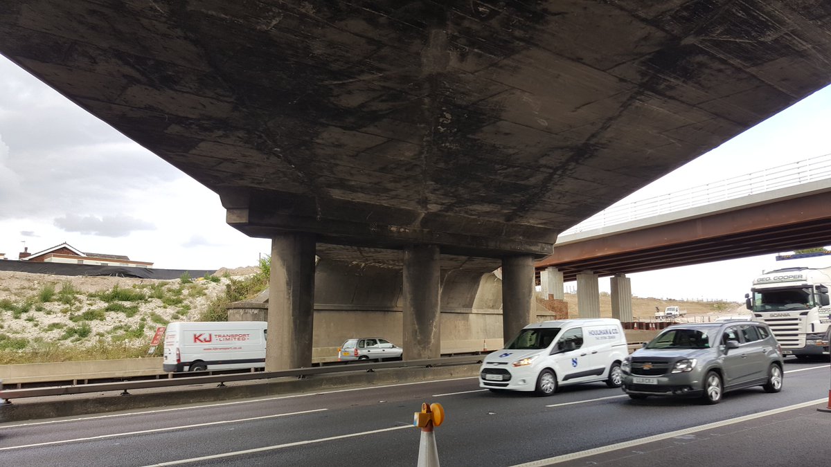
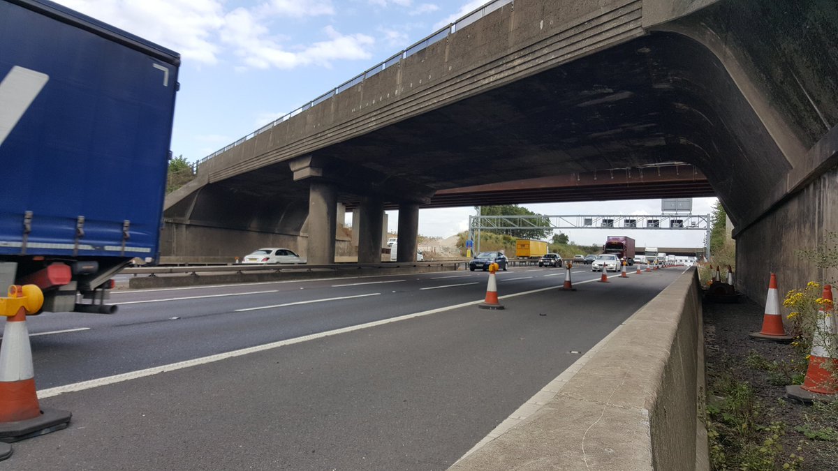
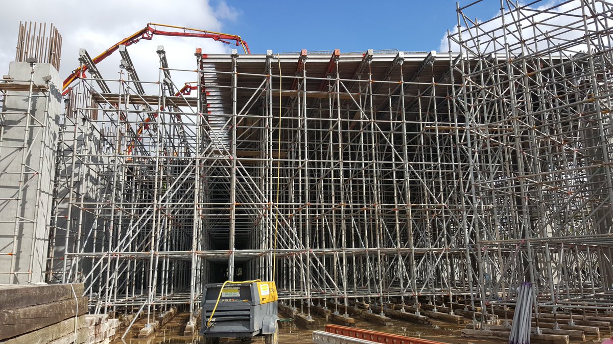
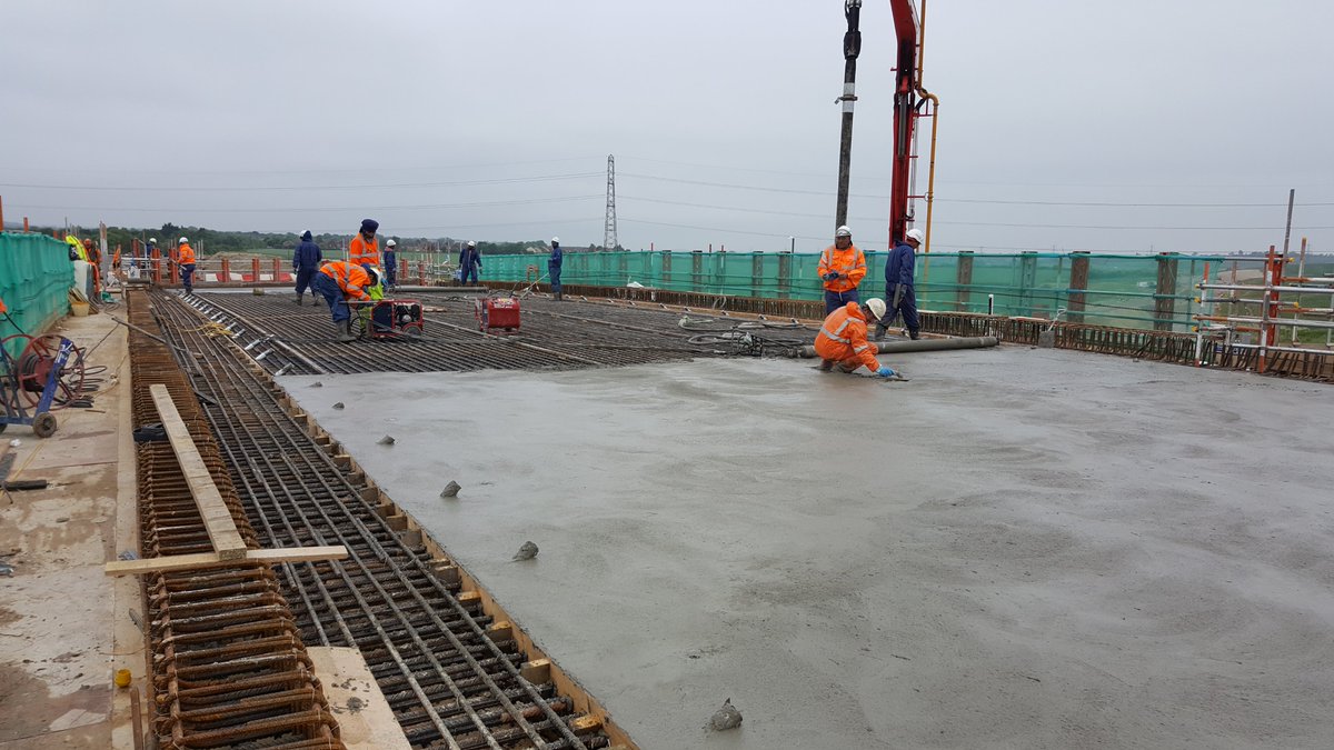
These bridges were built on new alignments, so offline, and allowed for traditional in-situ concrete decks. The deck is made from reinforced concrete, cast on a temporary soffit made from scaffolding. This technique is still used in places but less so, scaffolding is expensive!
You can’t put scaffolding on an existing road or rail line which is why this technique is best for offline structures. Most of the original M1 bridges between Watford Gap & St Albans were built this way.
If you look at the soffit of these bridges you can see straight lines running across – these are the where the joints in the plywood forming the soffit. The plywood was supported by the scaffold.
Once the concrete had cured and was self-supporting, the scaffolding removed, and voila – you have a bridge. This is also known as a traditional slab deck as that’s all it is – one big concrete slab. (Brief pause to type up the second half of this thread....)
A uniform slab can only span so far, around 20m. But increase the thickness of the concrete, and you can span further, 30-40m. However building all of this on site takes time, and time increases costs, so precast concrete is used.
Precast concrete are items or elements of a bridge that are cast separately, brought to the bridge location and installed in place. The casting can be done on site or elsewhere, but it allows other construction to continue.
For example, a lot of precast beams come from Ireland, sometimes taking weeks or months to build. You can do the piling and built abutments whilst the beams are being fabricated concurrently, saving time. The quality is better controlled in off-site conditions.
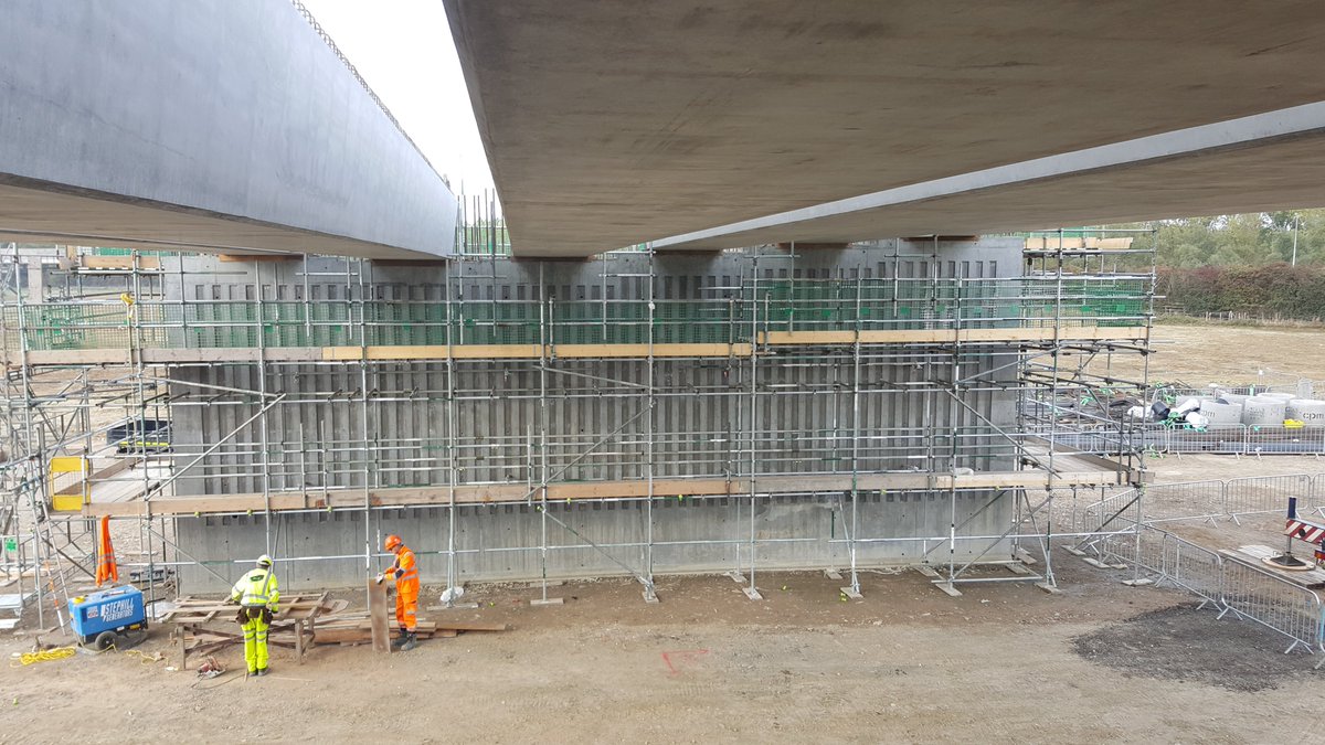
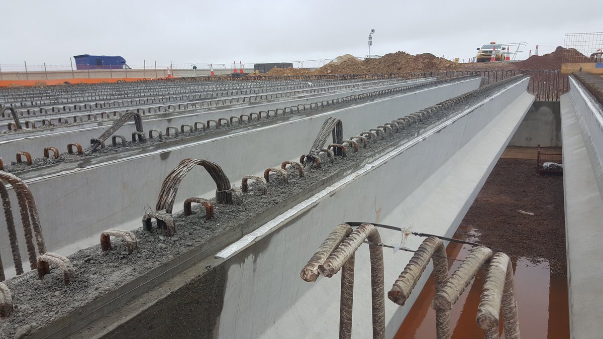
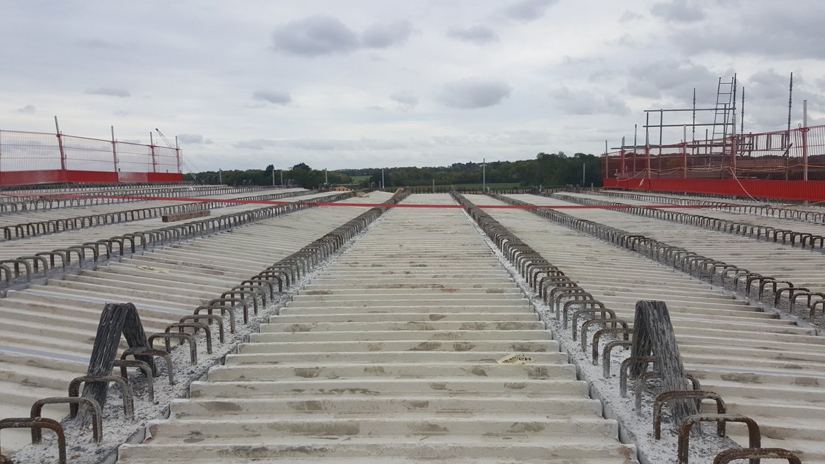
Precast beams come in multitudes of shapes and sizes, optimised for strength and efficiency. A thin concrete slab is still poured to tie / ‘stitch’ all the beams together, but the beams are transferring the bulk of the loads.
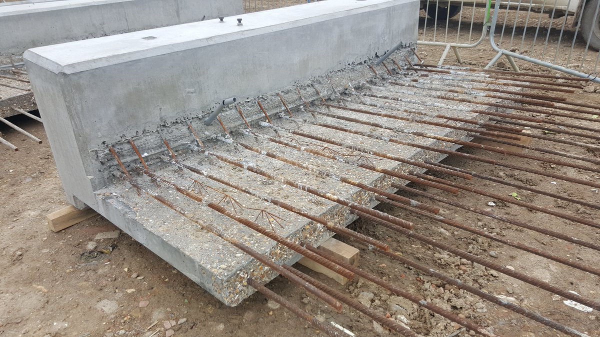
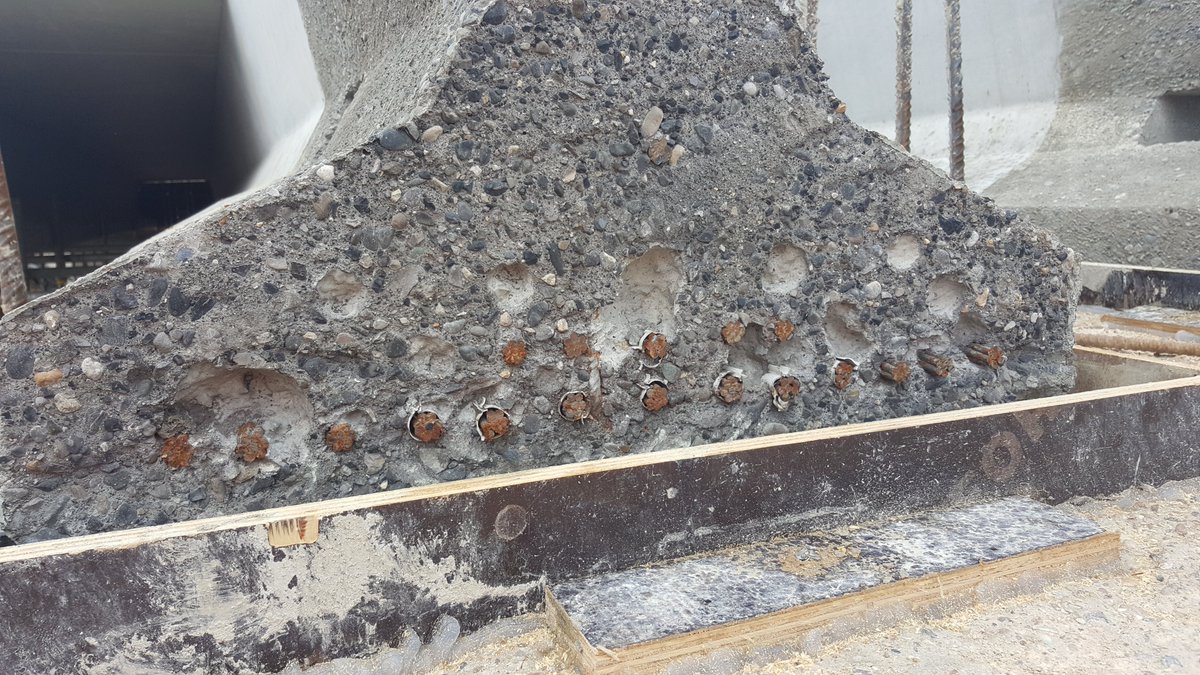
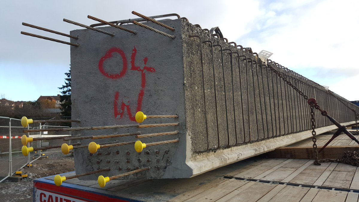
Concrete beams can be pretensioned for better strength. Steel wires are stretched through the beam mould, putting them under strain. The concrete is poured and once cured, the strands are released. The strands are sticking out the end of the beam in these pictures.
The strands want to spring & shrink back to their original length, this pulls the beam in from either end. Ever picked up a stack of books and turned them sidewards, pressing together with your hands to stop the middle books falling out? It’s the same principle, squeezing itself.
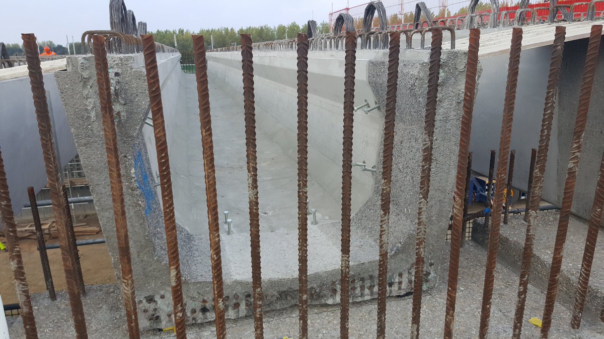
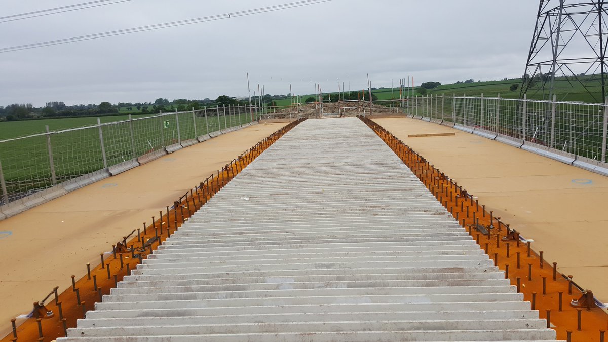
Beams can be adjacent or have a wider spacing. The soffit to stitch slab in the gaps between beams can be formed from plywood on scaffolding, or nowadays precast panels are fitted into place.
These precast panels can be made from glass-reinforced plastic; some come with steel ribs in for extra strength. They span between beams closing the gap, the concrete is poured on top and they are left in place.
The precast panels can also be thin concrete planks – the taxiway extension at London City Airport are being built with concrete planks spanning the dock.
Precast concrete beams can span around 40-50m, but you are also limited by what you can physically transport on roads around the country. To span further, you need to build bigger beams on site.
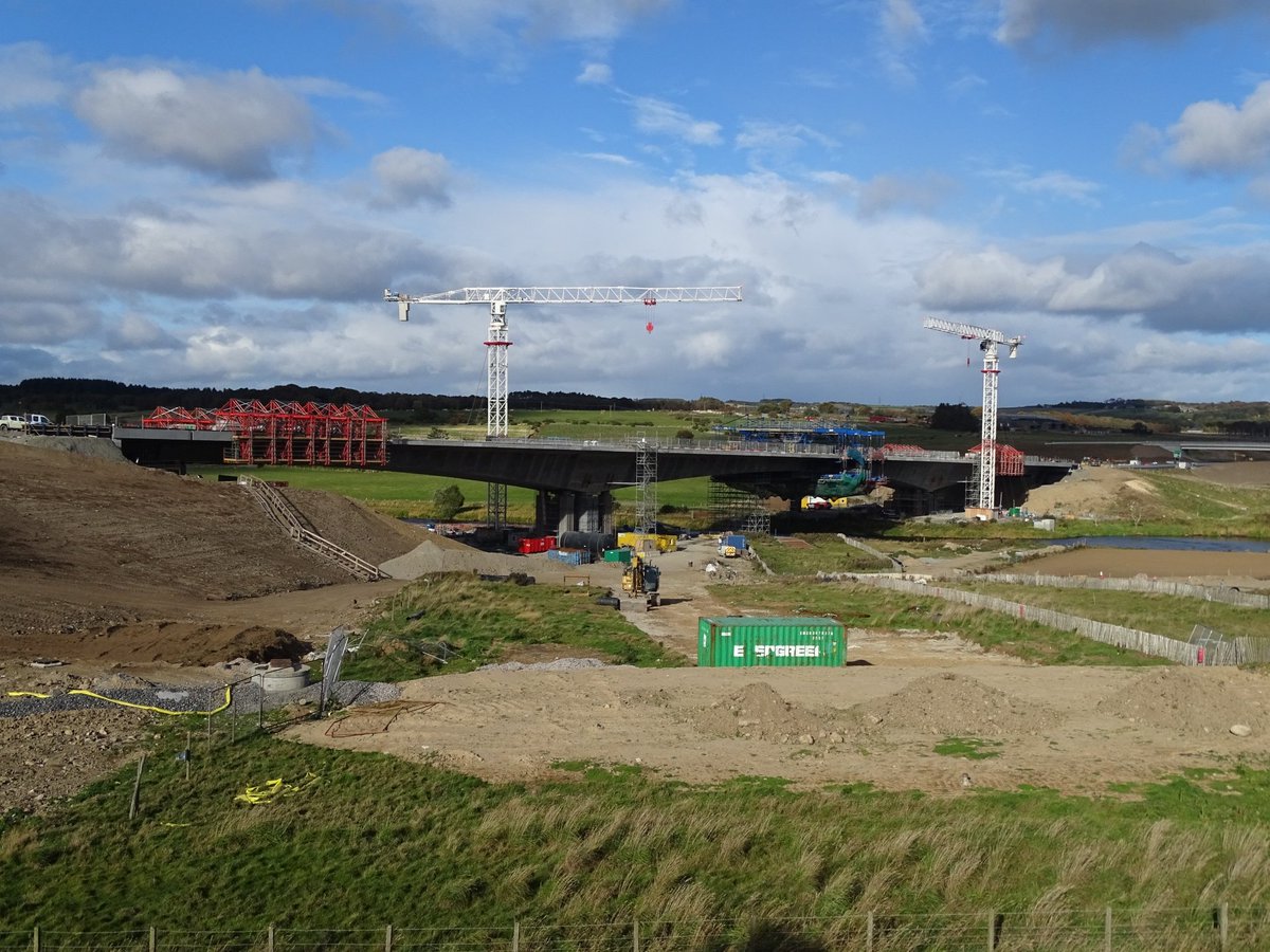
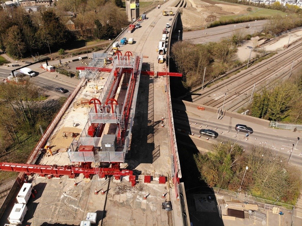
At this point it’s better to build slender concrete arches than flat beams. The arch & deck section is built out from the abutments or piers using a ‘travelling’ mould (formwork)
You pour a section, and move the formwork forwards. Cast the next section, move it again. The viaducts on the Aberdeen peripheral route were built using this method. Some major suspension bridges also cast their decks like this. The blue structures is the moving formwork:
In all of these examples discussed so far, the concrete is reinforced. Concrete is very poor in tension and decks, spanning gaps, are more in tension that compression. So steel reinforcing bar is used to deal with the tension.
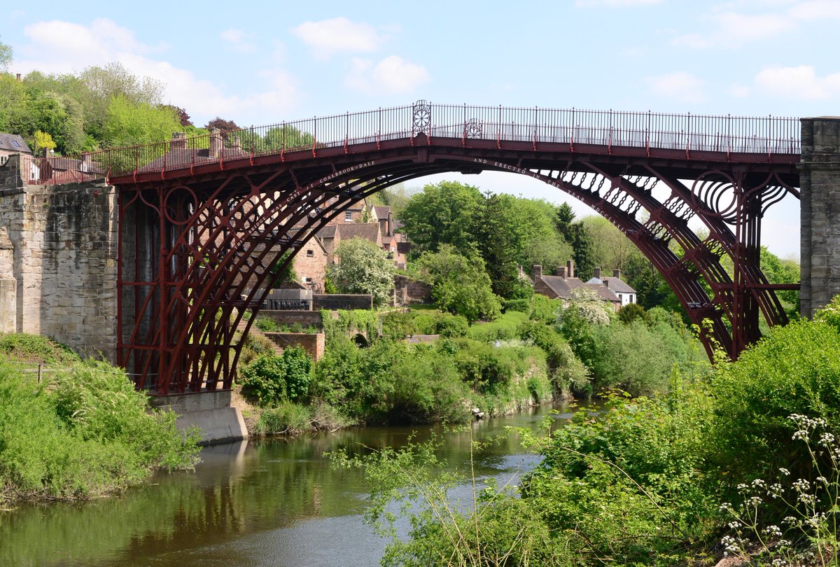
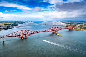
Speaking of steel – metal has been used for ages for bridges. Ironbridge and the Forth Rail bridge are popular examples. These structures have less of a defined ‘deck’ and more of a metal truss structure with a deck passing through.
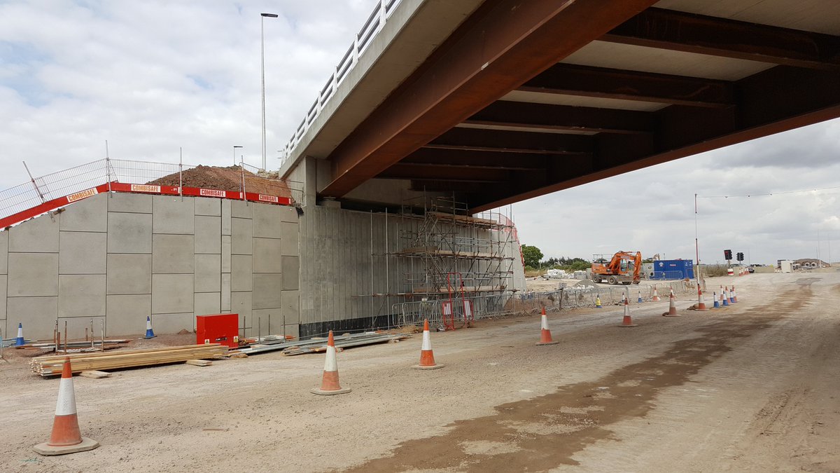
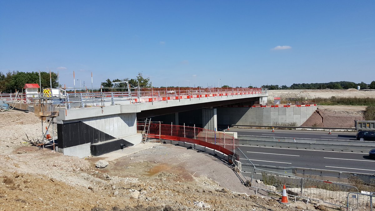
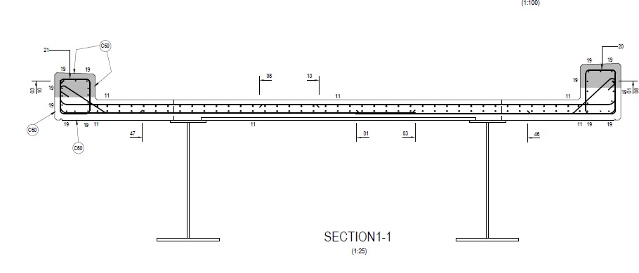
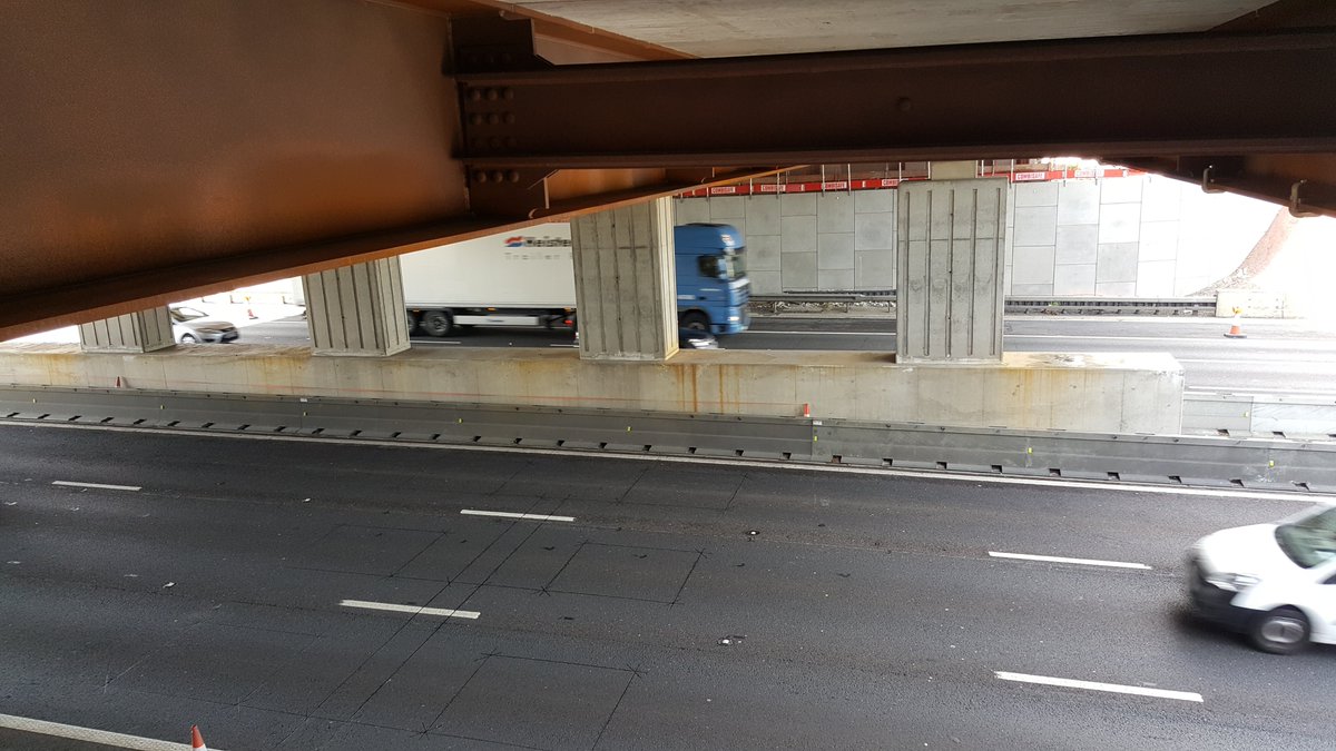
For basic bridges, we use steel for composite decks. Similar to precast concrete, steel beams span the gap and a thin concrete slab ties all of the beams together. Here we have steel beams supporting a concrete deck slab & parapets:
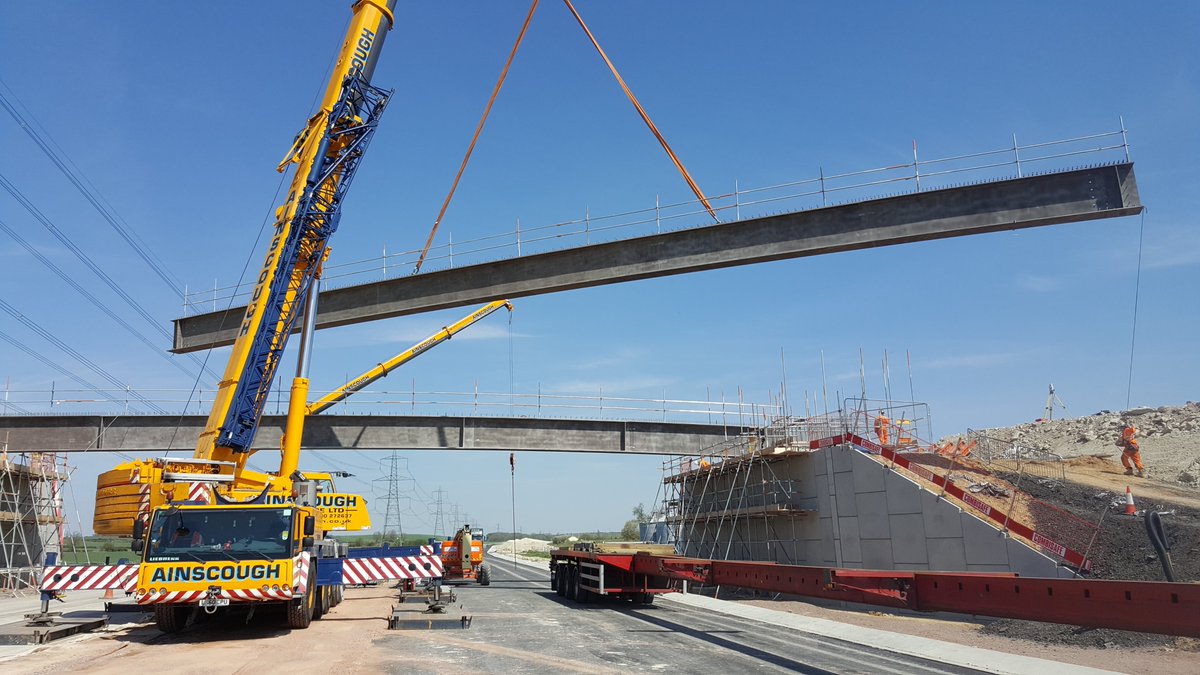
Structural beams are most often I-sections, with the vertical part of the ‘I’ (the web) giving the strength. The top and bottom horizontal parts are called the flange. Steel is again restricted by length for road transport but can be spliced or welded into longer sections.
The gaps between beams can again be spanned with GRP or precast concrete panels. Cross-beams, header beams and stiffener sections are used to help tie the steelwork together.
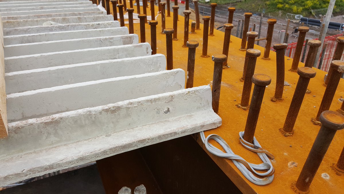
The studs sticking out of steel beams, and rebar hoops in precast beams, are known as shear studs & shear links, they key the concrete to the beam, similar to the fuzzy bits of velcro straps!
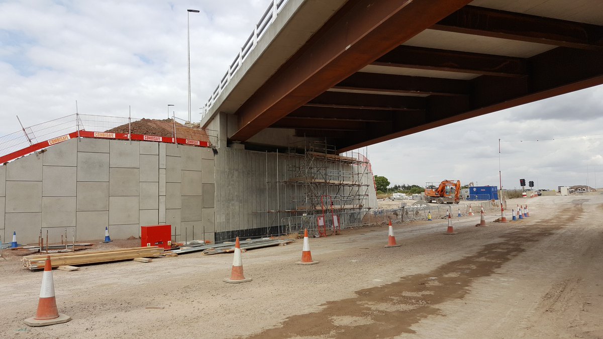
Why are a lot of steel beam bridges brown? That’s the rust. “But wait Alex, you were talking about how bad corrosion is earlier, why are brand-new beams all rusty being used on bridges?” Brand new steel is actually grey, as in this pic. It rusts to orange.
This is called ‘weathering steel’. The beam is allowed to rust, building up a layer approx. 1.5mm thick. The rust provides a protective barrier to the main beam core. The thickness of rust is monitored to ensure it's providing protection.
Painted steel beams look good – but they need repainting. This means closing the road or rail line, which is expensive. Better to let them rust and save some money, and not put people at risk working at height on around live traffic.
Steel beams with concrete decks are known as ‘composite decks’ as you are using two different structural materials. Beams can be 2m tall, but the concrete slab around 250mm thick.
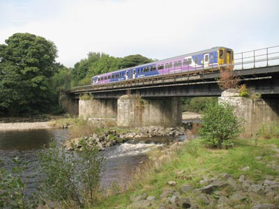
Some bridge decks can be entirely steel – most commonly for rail & canal bridges where they are lifted in one section to aid construction. Footbridges often have metal decks due to the light loadings.
Building online overbridges lends itself to beam & slab decks. The walls can be built either side of the road/rail, and the beams installed on night closures. The deck is then cast and the bridge is structurally sealed.
Online underbridges are trickier; sometimes the road is excavated out and precast units installed, or jacked under the road. M1 J15a features a box unit that was jacked underneath the motorway, and a similar idea is being done at Werrington Dive-under on the ECML.
The next big technique, used extensively in rail but becoming more common for roads, is building the deck offline for on-line bridges, and moving the deck into place once abutments are ready. This saves time as you build abutments and deck simultaneously.
This was used on the M56 Thorley Lane overbridge replacement. The deck was built in a fabrication yard near to the bridge location, jacked up on heavy-duty transporters and driven into place, landing on the abutments.
The A14 Cambridge to Huntingdon rebuilt the Bar Hill junction by installing the two junction bridges like this. I was fortunate to be involved in early concept work for this installation method. The bridges were built in a yard nearby & driven up the A14
Finally, @HS2ltd has used this method to install new bridges over the M42 and A446. Instead of two weeks of night closures, 18 hours is all that's needed to drive the bridges into place.
So after spending 1700 words talking about building bridges, lets u-turn and talk about how to demolish them! This part of the thread will be considerably shorter than the earlier sections:
You generally have three methods available. Let’s look at them in turn.
Dismantling: Carefully cutting up sections of the bridges and carefully removing them. This is slow and costly, but avoids creating damage. The old A14 Huntingdon viaduct was dismantled this way to keep the East Coast mainline operational below.
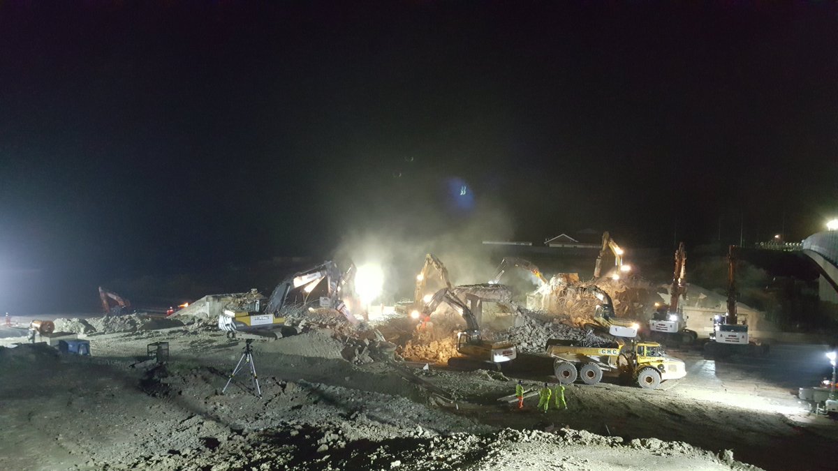
Demolishing: Excavators fitted with giant hydraulic breakers and claws munch away at the bridge, breaking it down. Seen a time-lapse of ants devouring an animal carcass? It’s much the same.
Finally, the one everyone loves: Explosives. If all else fails, just blow it up. Quick, but risky and costly as unsurprisingly, using explosives is tightly controlled. The M6 Catthorpe viaduct was blown up (I can't find the video annoyingly).
Demolition is the most common method, it’s relatively quick, easy to control and manage, although you still need to shut the road or rail line to do it.
Explosion is relatively rare, often it is written into contracts that explosives cannot be used. On the M1 J19 the design of existing bridges could’ve led to unsafe collapses if demolished, so they decided to blow them up instead.
I was fortunate enough to work on the demolition of two bridges over the M1 in Bedfordshire in 2016, more details, available in a previous thread here: https://twitter.com/russiankiwi3/status/1304323908447989761?s=20
Here's the start of the demolition - excavators with huge hydraulic breakers and grabs pull down the concrete parapets, before munching through the deck. It's a careful and tightly-controlled process to ensure the deck breaks safely. https://twitter.com/i/status/1304323908447989761
Here is a great video of that demolition from start to finish:
Again, by law designers are now required to consider and inform the asset owner of safe methods to decomission/demolish the structure/asset.
Again, by law designers are now required to consider and inform the asset owner of safe methods to decomission/demolish the structure/asset.
You can see the dust, it's noisy and messy. Timber mats are put down to protect the road, we also had surfacing crews on standby in case of damage. But it is an incredible operation to be part of.
Right, that’s the end of Part 3. I’ve mentioned them a few times; tomorrow we look more at why we need bearings and expansion joints! Hope you have enjoyed and will join me again tomorrow.
Image credits:
Lipwood rail bridge: https://images.app.goo.gl/XnjuFvXVuqAXnRAP9
Queensferry Crossing: https://images.app.goo.gl/sG52s2iN6vmyYrJ46
Ribblehead Viaduct: https://images.app.goo.gl/cHEAGNFt3Rv2zDmaA
London City Airport: https://images.app.goo.gl/3bBgWCz8d9pQkxg19
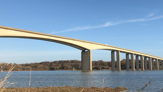
River Orwell Bridge: https://images.app.goo.gl/yUZmmUP8PpSkS8oKA
River Don Crossing #1: https://images.app.goo.gl/P3zg4Z1pAReK6FF86
River Don Crossing #2: https://images.app.goo.gl/Gt2kJLMG4JL5VHKq6
Ironbridge: https://images.app.goo.gl/VLBvnkru393MMZCS9
Forth Rail Bridge: https://images.app.goo.gl/xD7iWAJMKSi3Ydzj6
Google Streetview Images also used.
Otherwise my own images used, featuring A5-M1 & A14 schemes.
River Don Crossing #2: https://images.app.goo.gl/Gt2kJLMG4JL5VHKq6
Ironbridge: https://images.app.goo.gl/VLBvnkru393MMZCS9
Forth Rail Bridge: https://images.app.goo.gl/xD7iWAJMKSi3Ydzj6
Google Streetview Images also used.
Otherwise my own images used, featuring A5-M1 & A14 schemes.

 Read on Twitter